
User's Manual
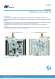

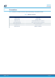
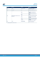
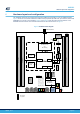
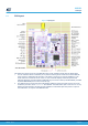

Table Of Contents
- 1 Features
- 2 Ordering information
- 3 Development environment
- 4 Conventions
- 5 Quick start
- 8 NUCLEO-WL55JC board information
- Appendix A STM32WL Nucleo-64 I/O assignment
- Appendix B Federal Communications Commission (FCC) and Innovation, Science and Economic Development Canada (ISED) Compliance Statements
- Appendix C Déclaration de conformité CE simplifiée
- Revision history
- Contents
- List of tables
- List of figures

Jumper Definition
Position
(1)
Comment
(1)
JP5 I_SYS OFF (SB27 ON)
For STM32WL current
measurements (Digital part)
JP6 STLK-RST OFF STLINK-V3E reset
JP7 5V_PWR ON 5 V power-source selection
JP8
Signals between STLINK-V3E and
MCU target
[1-2]
T_SWDIO connected to ST-
LINK
[3-4]
T_SWCLK connected to ST-
LINK
[5-6] T_SWO connected to ST-LINK
[7-8]
STLK_VCP_TX connected to
ST
-LINK
[9-10] T_NRST connected to ST-LINK
[11-12]
STLK_VCP_TX connected to
ST
-LINK
JP9 I_APP OFF (SB32 ON)
For U3 and U4 DC switches
current measurement
1.
Default jumper state is shown in bold.
UM2592
Getting started
UM2592 - Rev 2
page 7/50