
Datasheet

DocID5257 Rev 11 7/23
MC34063AB, MC34063AC, MC34063EB, MC34063EC Electrical characteristics
Note: Maximum package power dissipation limit must be observed.
If Darlington configuration is not used, care must be taken to avoid deep saturation of output
switch. The resulting switch-off time may be adversely affected. In a Darlington
configuration the following output driver condition is suggested:
Forced
of output current switch = I
COUTPUT
/(I
CDRIVER
- 1 mA)
10
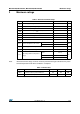
Table 8. Total device
Symbol Parameter Test conditions Min. Typ. Max. Unit
I
CC
Supply current
V
CC
= 5 to 40 V
C
T
= 1 nF
PIN 7 = V
CC
V
PIN5
>V
TH
PIN 2 = GND
Remaining pins
open
for MC34063A 2.5 4
mA
1.5 4for MC34063E
V
START-UP
Start-up voltage
(1)
T
A
= 25°C
C
T
= 1 µF, PIN 5 = 0
for MC34063A 2.1
V
for MC34063E 1.5
1. Start-up voltage is the minimum power supply voltage at which the internal oscillator begins to work.