UM2252 User manual Getting started with the X-NUCLEO-NFC05A1 NFC card reader expansion board based on ST25R3911B for STM32 Nucleo Introduction The X-NUCLEO-NFC05A1 NFC card reader expansion board is used to evaluate functions based on the ST25R3911B, designed for the expansion of STM32 Nucleo boards. It is compatible with the Arduino™ UNO R3 connector and can be plugged to any STM32 Nucleo board together with other expansion boards to evaluate different devices.
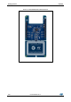
Getting started UM2252 Figure 1: X-NUCLEO-NFC05A1 expansion board 2/26 DocID030806 Rev 2
UM2252 Contents Contents 1 Getting started ................................................................................. 6 1.1 Hardware requirements ..................................................................... 6 1.2 System requirements ........................................................................ 6 2 Board setup ..................................................................................... 7 3 Hardware .................................................................
List of tables UM2252 List of tables Table 1: Interconnections between the X-NUCLEO-NFC05A1 expansion board and the Nucleo-L476RG board (left side) ........................................................................................................................................... 8 Table 2: Interconnections between the X-NUCLEO-NFC05A1 expansion board and the Nucleo-L476RG board (right side) ............................................................................................................
UM2252 List of figures List of figures Figure 1: X-NUCLEO-NFC05A1 expansion board ..................................................................................... 2 Figure 2: X-NUCLEO-NFC05A1 component placement .......................................................................... 10 Figure 3: STM32 Nucleo connector schematic diagram ........................................................................... 12 Figure 4: ST25R3911B schematic diagram ..............................................
Getting started 1 UM2252 Getting started Connect the X-NUCLEO-NFC05A1 to an STM32 Nucleo-64 development board. The PC USB port has to be capable of delivering at least 300 mA at 5 V supply. A demo software is available for download at www.st.com to be programmed onto the STM32 Nucleo. 1.
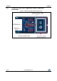
UM2252 2 Board setup Board setup To set up the board; 1 Connect the X-NUCLEO-NFC05A1 expansion board to the STM32 Nucleo board from the top through the Arduino® UNO R3 connectors 2 Power the STM32 Nucleo board using a Mini-B USB cable 3 Program the firmware on the STM32 Nucleo board using the provided example 4 Reset the MCU using the reset button available on the STM32 Nucleo board. The evaluation kit is ready to be used.
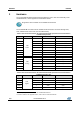
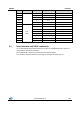
Hardware 3 UM2252 Hardware The X-NUCLEO-NFC05A1 expansion board allows the user to test the functionality of the ST25R3911B ICa, which supports the reader/writer modeb. Program the microcontroller on the STM32 Nucleo board. The ST25R3911B IC module and the STM32 Nucleo board are connected through CN5, CN6, CN8 and CN9 connectors (see the tables below).
UM2252 Hardware Signal Pin number Nucleo-L476RG X-NUCLEO-NFC05A1 D12 5 PA6 MISO_MCU D11 4 PA7 MOSI_MCU D10 3 PB6 /SS_MCU D9 2 PC7 - D8 1 PA9 - D7 8 PA8 MCU_LED6 D6 7 PB10 - D5 6 PB4 MCU_LED4 5 PB5 MCU_LED5 4 PB3 - D2 3 PA10 - D1 2 PA2 - D0 1 PA3 - D4 D3 3.1 Connector CN9 Digital Host interface and GPIO connection The X-NUCLEO-NFC05A1 expansion board contains the ST25R3911B-AQFT chip and is powered by the STM32 Nucleo board.
Hardware 3.
UM2252 Component description 4 Component description 4.
Component description UM2252 Figure 3: STM32 Nucleo connector schematic diagram 12/26 DocID030806 Rev 2
UM2252 4.2.2 Component description ST25R3911B schematic diagram The ST25R3911B is directly connected to the filtered 5 V USB supply. There are additional supply filtering components placed close to the NFC/HF reader IC. Jumper JP200 can be used to measure the chip supply current. If this measurement is performed, the ferrite beat L301 has to be removed. Capacitors 200 to 203 provide additional filtering of the ST25R3911B supply.
Component description UM2252 Figure 4: ST25R3911B schematic diagram 14/26 DocID030806 Rev 2
UM2252 4.2.3 Component description Antenna and matching network components This schematic diagram contains the matching network and the automatic antenna tuning capacitors as well as the alternative NFC Forum matching components. In the default configuration, the X-NUCLEO-NFC05A1 expansion board is populated with a VHBR tuning, which allows communication to speed up to 3.4 Mbps. The Q-factor is doubled and bitrates up to 848kbps are supported, by switching the components listed in the following table.
Component description UM2252 Figure 5: Matching circuit schematic diagram 16/26 DocID030806 Rev 2
UM2252 Component description 4.3 PCB Layout 4.3.1 PCB layers As the ST25R3911B is a high power RF transmitter, the NFC reader layout must be done carefully. The decoupling capacitors are located as close as possible to the positive and negative power supply pins (for example VSP_RF and VSN_RF). Since the chip is using a differential output driver stage, the antenna matching network is treated as a differential network.
Component description 4.3.3 UM2252 Mid layer 1 The mid layer 1 is a pure GND plane. It provides a low ohmic DC path for the GND connection. Figure 7: PCB layout mid layer 1 4.3.4 Mid layer 2 Mid layer 2 is used for power distribution. It contains the power planes for the ST25R3911B 5 V supply and the 3.3 V to communicate with the STM32 Nucleo board.
UM2252 4.3.5 Component description Bottom layer The bottom layer is mainly GND plane. Some traces are routed through the bottom plane.
Bill of materials 5 UM2252 Bill of materials Table 4: X-NUCLEO-NFC05A1 bill of materials Item Q.ty Ref. Manufacturer Order code 1 0 C202 DNM 2 0 J300 DNM 3 0 J301 DNM 4 0 JP200 DNM 5 0 C303, C306 DNM 6 0 J200, J202 DNM 7 1 C100 0402, 0.01 µF, 25 V, ± 10%, X7R AVX 0402YC101KAT2A 8 5 C101, C208, C209, C210, C211 0402, 0.01 µF, 25 V, ± 10%, X7R AVX 04023C103KAT2A 9 0 P200, P201 DNM HRS (HIROSE) U.
UM2252 Bill of materials Item Q.ty Ref.
Bill of materials Item Q.ty Ref. Part/Value Manufacturer Order code 30 8 R101, R102, R103, R104, R105, R106, R205, R206 1 kohm, 50 V, 0402, >100 mW, ± 5% Panasonic ERJ2GEJ102X 31 1 CN5 Header 10X1_Femal e Samtec SSQ-110-03-L-S 32 1 CN8 Header 6X1_Female Samtec SSQ-106-03-L-S 33 2 CN6, CN9 Header 8X1_Female Samtec SSQ-108-03-L-S 34 1 U200 ST ST25R3911B-AQFT 35 2 R300_NF CF, R301_NF CF 1.96 Ohm ±1% 0.
UM2252 Federal Communications Commission (FCC) and Industry Canada (IC) compliance 6 Federal Communications Commission (FCC) and Industry Canada (IC) compliance 6.1 FCC Compliance Statement 6.1.1 Part 15.19 This device complies with Part 15 of the FCC Rules. Operation is subject to the following two conditions: (1) this device may not cause harmful interference, and (2) this device must accept any interference received, including interference that may cause undesired operation. 6.1.2 Part 15.
Federal Communications Commission (FCC) and Industry Canada (IC) compliance tout brouillage radioélectrique subi, même si le brouillage est susceptible d’en compromettre le fonctionnement. 6.2.
UM2252 7 Revision history Revision history Table 5: Document revision history Date Version Changes 06-Jul-2017 1 Initial release 31-Jul-2017 2 Added Section 6.1.3: "Part 15.
UM2252 IMPORTANT NOTICE – PLEASE READ CAREFULLY STMicroelectronics NV and its subsidiaries (“ST”) reserve the right to make changes, corrections, enhancements, modifications, and improvements to ST products and/or to this document at any time without notice. Purchasers should obtain the latest relevant information on ST products before placing orders. ST products are sold pursuant to ST’s terms and conditions of sale in place at the time of order acknowledgement.