
User's Manual

UM2252
Component description
DocID030806 Rev 2
13/26
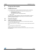
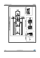
4.2.2 ST25R3911B schematic diagram
The ST25R3911B is directly connected to the filtered 5 V USB supply. There are additional
supply filtering components placed close to the NFC/HF reader IC.
Jumper JP200 can be used to measure the chip supply current.
If this measurement is performed, the ferrite beat L301 has to be removed.
Capacitors 200 to 203 provide additional filtering of the ST25R3911B supply.
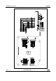
During layout all decoupling capacitors have been placed as close as possible to the
ST25R3911B chip. Special care has been taken for C209, C201, C213 and C200 since
these decoupling capacitors are used for the high power driver stage.
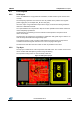
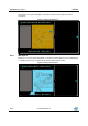
To demonstrate the capacitive wake-up feature, two capacitive electrodes are placed on
the PCB. Additional electrodes can be connected using the P200 and P201 UFL
connectors.
For SPI cross-connecting another reader PCB, the resistors R200 to R204 can be
removed.
J201 allows to bypass the internal VSP_RF regulator in case the output current is > 200
mA and needs to be supported.