
User manual
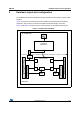


Table Of Contents
- Figure 1. STM32 Nucleo-64 board (1)
- 1 Ordering information
- 2 Conventions
- 3 Quick start
- 4 Features
- 5 Hardware layout and configuration
- 6 Mechanical drawing
- 7 Electrical schematics
- 8 References
- 9 Revision history
Hardware layout and configuration UM1724
12/61 DocID025833 Rev 9
5.2.3 Using the ST-LINK/V2-1 to program/debug the STM32 on board
To program the STM32 on the board, plug in the two jumpers on CN2, as shown in red in
Figure 6. Do not use the CN4 connector as this could disturb the communication with the
STM32 microcontroller of the STM32 Nucleo board.
Figure 6. Connecting the STM32 Nucleo board to program the on-board STM32
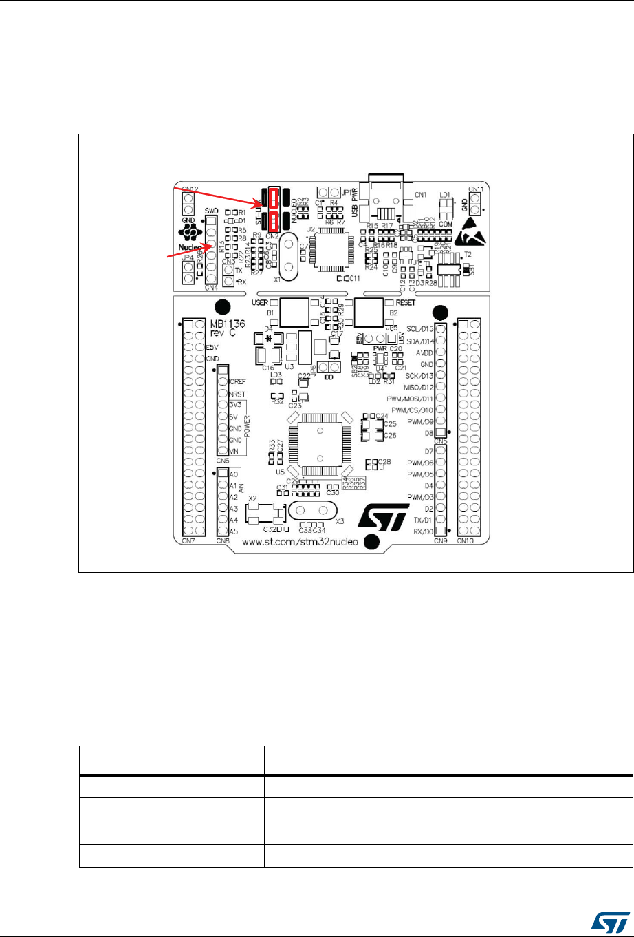
5.2.4 Using ST-LINK/V2-1 to program/debug an external STM32 application
It is very easy to use the ST-LINK/V2-1 to program the STM32 on an external application.
Simply remove the two jumpers from CN2 as illustrated in
Figure 7, and connect the
application to the CN4 debug connector according to Table 4.
Note: SB12 NRST (target MCU RESET) must be OFF if CN4 pin 5 is used in the external
application.
069
EϮũƵŵƉĞƌƐKE
Eϰ^t
ĐŽŶŶĞĐƚŽƌ
Table 4. Debug connector CN4 (SWD)
Pin CN4 Designation
1 VDD_TARGET VDD from application
2 SWCLK SWD clock
3 GND Ground
4 SWDIO SWD data input/output