
User manual

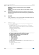


Table Of Contents
- Figure 1. STM32 Nucleo-64 board (1)
- 1 Ordering information
- 2 Conventions
- 3 Quick start
- 4 Features
- 5 Hardware layout and configuration
- 6 Mechanical drawing
- 7 Electrical schematics
- 8 References
- 9 Revision history
DocID025833 Rev 9 17/61
UM1724 Hardware layout and configuration
60
5.3.3 External power supply input: + 3V3
It can be of interest to use the +3V3 (CN6 pin 4 or CN7 pin 12 and pin 16) directly as power
input for instance in case the 3.3
V is provided by an extension board. When NUCLEO is
power supplied by +3V3, the ST-LINK is not powered thus the programming and debug
features are unavailable. The external power sources +3.3V is summarized in the
Table 8.
Two different configurations are possible to use +3V3 to power the board:
• ST-LINK is removed (PCB cut), or
• SB2 (3V3 regulator) & SB12 (NRST) are OFF.
5.3.4 External power supply output
When powered by USB, VIN or E5V, the +5V (CN6 pin 5 or CN7 pin 18) can be used as
output power supply for an Arduino shield or an extension board. In this case, the maximum
current of the power source specified in
Table 6 needs to be respected.
The +3.3 V (CN6 pin 4 or CN7 pin 12 & 16) can be used also as power supply output. The
current is limited by the maximum current capability of the regulator U4 (500
mA max).
5.4 LEDs
The tricolor LED (green, orange, red) LD1 (COM) provides information about ST-LINK
communication status. LD1 default color is red. LD1 turns to green to indicate that
communication is in progress between the PC and the ST-LINK/V2-1, with the following
setup:
• Slow blinking Red/Off: at power-on before USB initialization
• Fast blinking Red/Off: after the first correct communication between the PC and ST-
LINK/V2-1 (enumeration)
• Red LED On: when the initialization between the PC and ST-LINK/V2-1 is complete
• Green LED On: after a successful target communication initialization
• Blinking Red/Green: during communication with target
• Green On: communication finished and successful.
• Orange On: Communication failure
User LD2: the green LED is a user LED connected to Arduino signal D13 corresponding to
MCU I/O PA5 (pin 21) or PB13 (pin 34) depending on the STM32 target. Please refer to
Table 10 to Table 21.
• When the I/O is HIGH value, the LED is on.
• When the I/O is LOW, the LED is off.
LD3 PWR: the red LED indicates that the MCU part is powered and +5V power is available.
Table 8. +3.3V eternal power source
Input power
name
Connectors pins Voltage range Limitation
+3V3
CN6 pin 4
CN7 pin 12 and pin 16
3 V to 3.6 V
Used when ST-LINK part of PCB is cut or
SB2 and SB12 OFF