
User manual


Table Of Contents
- Figure 1. STM32 Nucleo-64 board (1)
- 1 Ordering information
- 2 Conventions
- 3 Quick start
- 4 Features
- 5 Hardware layout and configuration
- 6 Mechanical drawing
- 7 Electrical schematics
- 8 References
- 9 Revision history
Hardware layout and configuration UM1724
20/61 DocID025833 Rev 9
5.7 USART communication
The USART2 interface available on PA2 and PA3 of the STM32 microcontroller can be
connected to ST-LINK MCU, STMicroelectronics Morpho connector or to Arduino connector.
The choice can be changed by setting the related solder bridges. By default the USART2
communication between the target MCU and ST-LINK MCU is enabled in order to support
Virtual Com Port for mbed (SB13 and SB14 ON, SB62 and SB63 OFF). If the
communication between the target MCU PA2 (D1) or PA3 (D0) and shield or extension
board is required, SB62 and SB63 should be ON, SB13 and SB14 should be OFF. In such
case it possible to connect another USART to ST-LINK MCU using flying wires between
Morpho connector and CN3. For instance on NUCLEO-F103RB it is possible to use
USART3 available on PC10 (TX) & PC11 (RX). Two flying wires need to be connected as
follow:
• PC10 (USART3_TX) available on CN7 pin 1 to CN3 pin RX
• PC11 (USART3_RX) available on CN7 pin 2 to CN3 pin TX
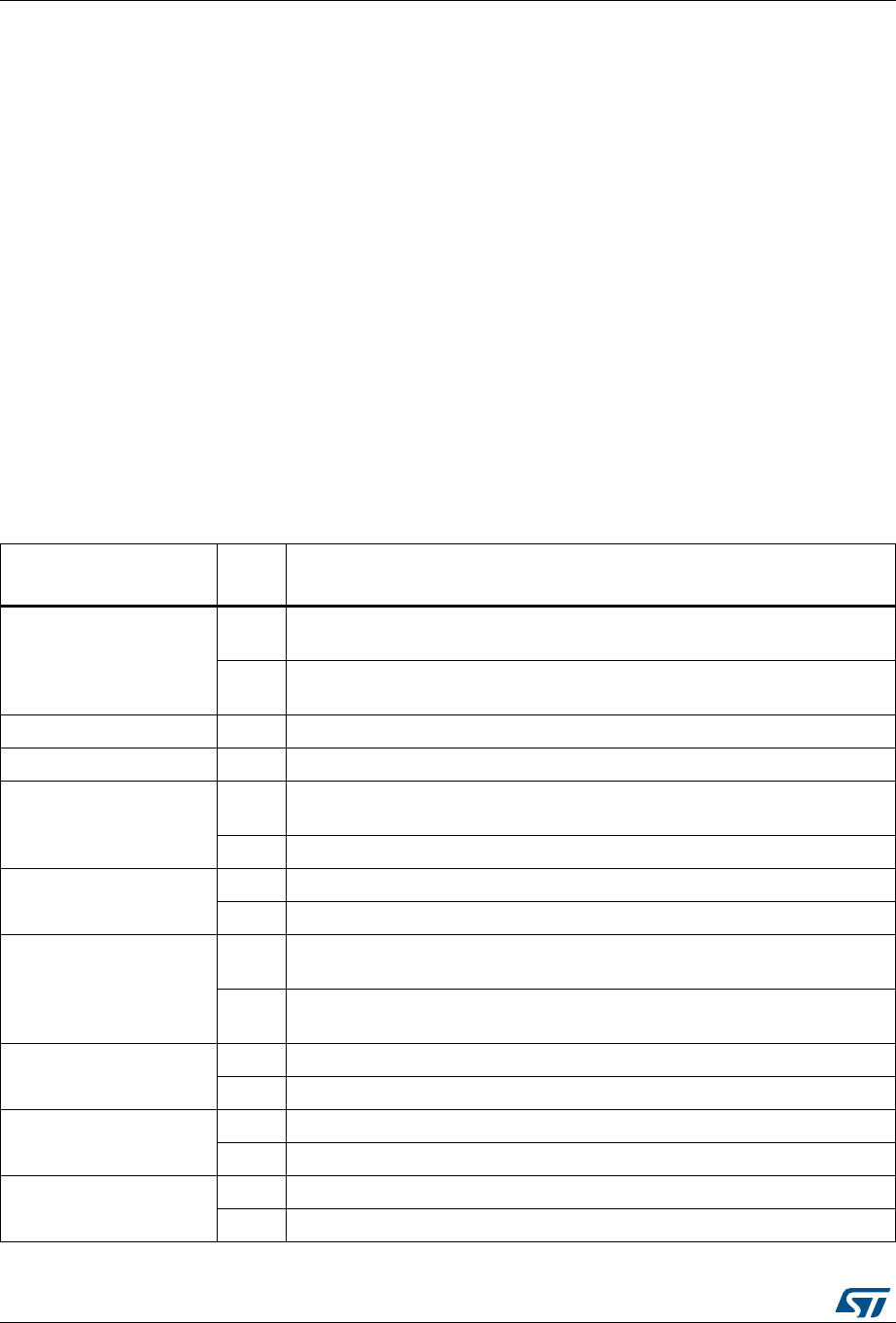
5.8 Solder bridges
Table 9. Solder bridges
Bridge
State
(1)
Description
SB54, SB55 (X3 crystal)
(2)
OFF
X3, C33, C34, R35 and R37 provide a clock as shown in Chapter 7: Electrical
schematics PF0/PD0/PH0, PF1/PD1/PH1 are disconnected from CN7.
ON
PF0/PD0/PH0, PF1/PD1/PH1 are connected to CN12. (R35, R37 and SB50
must not be fitted).
SB3,5,7,9 (DEFAULT) ON
Reserved, do not modify.
SB4,6,8,10 (RESERVED) OFF
Reserved, do not modify.
SB48,49
(X2 crystal)
(3)
OFF
X2, C31, C32, R34 and R36 deliver a 32 kHz clock. PC14, PC15 are not
connected to CN7.
ON
PC14, PC15 are only connected to CN7. Remove only R34, R36
SB17
(B1-USER)
ON
B1 push button is connected to PC13.
OFF
B1 push button is not connected to PC13.
SB12 (NRST)
ON
The NRST signal of the CN4 connector is connected to the NRST pin of the
STM32 MCU.
OFF
The NRST signal of the CN4 connector is not connected to the NRST pin of
the STM MCU.
SB15 (SWO)
ON
The SWO signal of the CN4 connector is connected to PB3.
OFF
The SWO signal is not connected.
SB11 (STM_RST)
OFF
No incidence on STM32F103CBT6 (ST-LINK MCU) NRST signal.
ON
STM32F103CBT6 (ST-LINK MCU) NRST signal is connected to GND.
SB1 (USB-5V)
OFF
USB power management is functional.
ON
USB power management is disabled.