
User manual


Table Of Contents
- Figure 1. STM32 Nucleo-64 board (1)
- 1 Ordering information
- 2 Conventions
- 3 Quick start
- 4 Features
- 5 Hardware layout and configuration
- 6 Mechanical drawing
- 7 Electrical schematics
- 8 References
- 9 Revision history
DocID025833 Rev 9 21/61
UM1724 Hardware layout and configuration
60
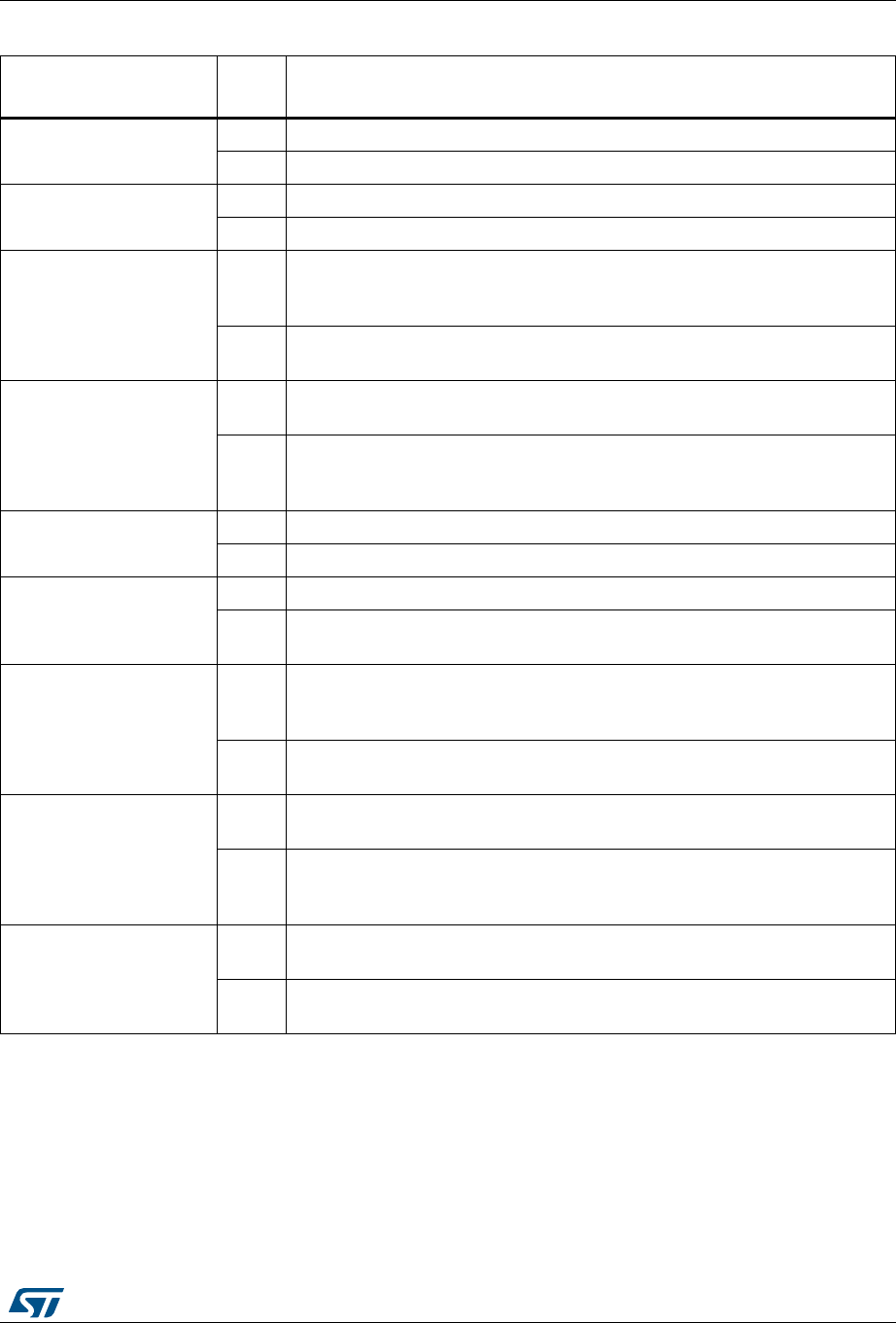
All the other solder bridges present on the STM32 Nucleo board are used to configure
several IOs and power supply pins for compatibility of features and pinout with STM32 MCU
supported.
SB2 (3.3 V)
ON
Output of voltage regulator LD39050PU33R is connected to 3.3V.
OFF
Output of voltage regulator LD39050PU33R is not connected.
SB21 (LD2-LED)
ON
Green user LED LD2 is connected to D13 of Arduino signal.
OFF
Green user LED LD2 is not connected.
SB56,SB51 (A4 and A5)
ON
PC1 and PC0 (ADC in) are connected to A4 and A5 (pin 5 and pin 6) on
Arduino connector CN8 and ST Morpho connector CN7. Thus SB46 and
SB52 should be OFF.
OFF
PC1 and PC0 (ADC in) are disconnected to A4 and A5 (pin 5 and pin 6) on
Arduino connector CN8 and ST Morpho connector CN7.
SB46,SB52
(I2C on A4 and A5)
OFF
PB9 and PB8 (I2C) are disconnected to A4 and A5 (pin 5 and pin 6) on
Arduino connector CN8 and ST Morpho connector CN7.
ON
PB9 and PB8 (I2C) are connected to A4 and A5 (pin 5 and pin 6) on Arduino
connector CN8 and ST Morpho connector CN7 as I2C signals. Thus SB56
and SB51 should be OFF.
SB45 (VBAT/VLCD)
ON
VBAT or VLCD on STM32 MCU is connected to VDD.
OFF
VBAT or VLCD on STM32 MCU is not connected to VDD.
SB57 (VDDA/VREF+)
ON
VDDA/VREF+ on STM32 MCU is connected to VDD.
OFF
VDDA/VREF+ on STM32 MCU is not connected to VDD and can be provided
from pin 7 of CN10
SB62, SB63 (USART)
ON
PA2 and PA3 on STM32 MCU are connected to D1 and D0 (pin 2 and pin 1)
on Arduino connector CN9 and ST Morpho connector CN10 as USART
signals. Thus SB13 and SB14 should be OFF.
OFF
PA2 and PA3 on STM32 MCU are disconnected to D1 and D0 (pin 2 and pin
1) on Arduino connector CN9 and ST Morpho connector CN10.
SB13, SB14
(ST-LINK-USART)
OFF
PA2 and PA3 on STM32F103CBT6 (ST-LINK MCU) are disconnected to PA3
and PA2 on STM32 MCU.
ON
PA2 and PA3 on STM32F103CBT6 (ST-LINK MCU) are connected to PA3
and PA2 on STM32 MCU to have USART communication between them.
Thus SB61,SB62 and SB63 should be OFF.
SB16,SB50(MCO)
(2)
OFF
MCO on STM32F103CBT6 (ST-LINK MCU) are disconnected to
PF0/PD0/PH0 on STM32 MCU.
ON
MCO on STM32F103CBT6 (ST-LINK MCU) are connected to PF0/PD0/PH0
on STM32 MCU.
1. The default SBx state is shown in bold.
2. Default configuration depends on board version. Please refer to chapter 5.7.1 for details
3. Default configuration depends on board version. Please refer to chapter 5.7.2 for details.
Table 9. Solder bridges (continued)
Bridge
State
(1)
Description