User manual
Manuals
Brands
STMICROELECTRONICS Manuals
Dev Kits
PCB design board
51
52
53
54
55
56
57
58
59
60
Table Of Contents
Figure 1. STM32 Nucleo-64 board (1)
1 Ordering information
2 Conventions
3 Quick start
3.1 Getting started
3.2 System requirements
3.3 NUCLEO-L476RG bootloader limitations
4 Features
4.1 Hardware configuration variants
5 Hardware layout and configuration
5.1 Cuttable PCB
5.2 Embedded ST-LINK/V2-1
5.2.1 Driver
5.2.2 ST-LINK/V2-1 firmware upgrade
5.2.3 Using the ST-LINK/V2-1 to program/debug the STM32 on board
5.2.4 Using ST-LINK/V2-1 to program/debug an external STM32 application
5.3 Power supply and power selection
5.3.1 Power supply input from the USB connector
5.3.2 External power supply inputs: VIN and EV5
Using VIN or E5V as external power supply
5.3.3 External power supply input: + 3V3
5.3.4 External power supply output
5.4 LEDs
5.5 Push buttons
5.6 JP6 (IDD)
5.6.1 OSC clock supply
5.6.2 OSC 32 kHz clock supply
5.7 USART communication
5.8 Solder bridges
5.9 Extension connectors
5.10 Arduino connectors
5.11 STMicroelectronics Morpho connector
6 Mechanical drawing
7 Electrical schematics
8 References
9 Revision history
DocID025833 Rev 9
53/61
UM1724
Mechanical drawing
60
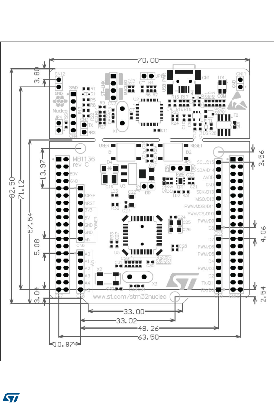
6 Mechanical
drawing
Figure
24. STM32 Nu
cleo board m
echanical d
rawing
1
...
...
55
56
57
58
59
...
...
65