
Datasheet

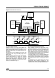

R
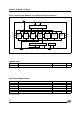
CC
XTI2DSPCLK
XTI2OCLK
X
S
N
M
PFD CP
VCO
Switchin
g
Circuit
OCLK
DCLK
U
p
date FRAC
FRAC
XTI
Disable PLL
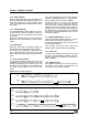
Figure 7.
PLL and Clocks Generation System
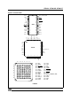
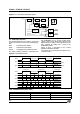
2.4 - PCM Output Interface
The decoded audio data are output in serial PCM
format. The interface consists of the following sig-
nals:
SDO PCM Serial Data Output
SCKT PCM Serial Clock Output
LRCLK Left/Right Channel Selection Clock
The output samples precision is selectable from
16 to 24 bits/word, by setting the output precision
with PCMCONF (16, 18, 20 and 24 bits mode)
register. Data can be output either with the most
significant bit first (MS) or least significant bit first
(LS), selected by writing into a flag of the
PCMCONF register.
Figure 8 gives a description of the several
STA013 PCM Output Formats.
The sample rates set decoded by STA013 is de-
scribed in Table 1.
LRCKT
SDO
SDO
PCM_FORMAT = 0
PCM_DIFF = 0
PCM_FORMAT = 1
PCM_DIFF = 1
32 SCLK C
y
cles
32 SCLK C
y
cles
32 SCLK C
y
cles
32 SCLK C
y
cles
32 SCLK C
y
cles
M
S
M
S
L
S
L
S
L
S
L
S
M
S
M
S
M
S
L
S
M
S
L
S
L
S
L
S
M
S
M
S
LRCKT
SDO
SDO
PCM_ORD = 1
PCM_PREC is 16 bit mode
PCM_ORD = 0
PCM_PREC is 16 bit mode
16 SCLK C
y
cles
16 SCLK C
y
cles
16 SCLK C
y
cles
16 SCLK C
y
cles
16 SCLK C
y
cles
M
S
M
S
L
S
L
S
L
S
L
S
M
S
M
S
M
S
L
S
M
S
L
S
L
S
L
S
M
S
M
S
SDO
PCM_FORMAT = 0
PCM_DIFF = 1
L
S
L
S
M
S
M
S
M
S
L
S
L
S
M
S
SDO
PCM_FORMAT = 1
PCM_DIFF = 1
L
S
L
S
M
S
M
S
M
S
L
S
L
S
M
S
0
0
00
0
0
0
0
00
00
0
0
0
0
MSBMSB
MSB MSB
Figure 8.
PCM Output Formats
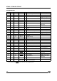
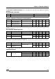
Table 1: MPEG Sampling Rates (KHz)
MPEG 1 MPEG 2 MPEG 2.5
48 24 12
44.1 22.05 11.025
32 16 8
STA013 - STA013B - STA013T
8/38