
Datasheet


DocID024711 Rev 5 3/33
STCC2540 List of figures
33
List of figures
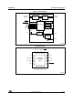
Figure 1. Block diagram . . . . . . . . . . . . . . . . . . . . . . . . . . . . . . . . . . . . . . . . . . . . . . . . . . . . . . . . . . . . 4
Figure 2. Pinout . . . . . . . . . . . . . . . . . . . . . . . . . . . . . . . . . . . . . . . . . . . . . . . . . . . . . . . . . . . . . . . . . . 4
Figure 3. Timing waveforms. . . . . . . . . . . . . . . . . . . . . . . . . . . . . . . . . . . . . . . . . . . . . . . . . . . . . . . . 10
Figure 4. Typical application diagram . . . . . . . . . . . . . . . . . . . . . . . . . . . . . . . . . . . . . . . . . . . . . . . . 11
Figure 5. State machine. . . . . . . . . . . . . . . . . . . . . . . . . . . . . . . . . . . . . . . . . . . . . . . . . . . . . . . . . . . 14
Figure 6. Power switch ON resistance vs. temperature . . . . . . . . . . . . . . . . . . . . . . . . . . . . . . . . . . . 18
Figure 7. OUT discharge resistance vs. temperature . . . . . . . . . . . . . . . . . . . . . . . . . . . . . . . . . . . . 18
Figure 8. OUT short-circuit current limit vs. temperature (R
ILIM
= 96 k) . . . . . . . . . . . . . . . . . . . . . 19
Figure 9. OUT short-circuit current limit vs. temperature (R
ILIM
= 33 k) . . . . . . . . . . . . . . . . . . . . . 19
Figure 10. OUT short-circuit current limit vs. temperature (R
ILIM
= 19.6 k). . . . . . . . . . . . . . . . . . . . 20
Figure 11. Disabled IN supply current vs. temperature . . . . . . . . . . . . . . . . . . . . . . . . . . . . . . . . . . . . 20
Figure 12. Enabled IN supply current vs. temperature (SDP mode) . . . . . . . . . . . . . . . . . . . . . . . . . . 21
Figure 13. Enabled IN supply current vs. temperature (CDP mode) . . . . . . . . . . . . . . . . . . . . . . . . . . 21
Figure 14. Enabled IN supply current vs. temperature (DCP auto-mode) . . . . . . . . . . . . . . . . . . . . . . 22
Figure 15. Enabled IN supply current vs. temperature (DCP BC1.2 mode). . . . . . . . . . . . . . . . . . . . . 22
Figure 16. Enabled IN supply current vs. temperature (DCP divider mode) . . . . . . . . . . . . . . . . . . . . 23
Figure 17. Data switch transfer characteristics vs. frequency . . . . . . . . . . . . . . . . . . . . . . . . . . . . . . . 23
Figure 18. Eye diagram using USB compliance test pattern - without STCC2540
(deskew line + cable) . . . . . . . . . . . . . . . . . . . . . . . . . . . . . . . . . . . . . . . . . . . . . . . . . . . . . 24
Figure 19. Eye diagram using USB compliance test pattern - with STCC2540
(STCC2540 + cable) . . . . . . . . . . . . . . . . . . . . . . . . . . . . . . . . . . . . . . . . . . . . . . . . . . . . . . 24
Figure 20. Turn-on response (RILIM = 20 k, R
LOAD
= 5 , C
LOAD
= 150 µF). . . . . . . . . . . . . . . . . . 25
Figure 21. Turn-off response (R
LOAD
= 5 , C
LOAD
= 150 µF) . . . . . . . . . . . . . . . . . . . . . . . . . . . . . . 25
Figure 22. Device enabled into short-circuit (R
ILIM
= 80.6 k) . . . . . . . . . . . . . . . . . . . . . . . . . . . . . . 26
Figure 23. Device enabled into short-circuit - thermal cycling (R
ILIM
= 20 k) . . . . . . . . . . . . . . . . . . 26
Figure 24. Short-circuit to full load recovery (R
ILIM
= 20 k, R
LOAD
= 5 , C
LOAD
= 150 µF) . . . . . . . 27
Figure 25. VFQFPN 16L 3 x 3 x 0.8 mm with exposed pad 1.7 package outline . . . . . . . . . . . . . . . . 28
Figure 26. VFQFPN 16L 3 x 3 x 0.8 mm with exposed pad 1.7 footprint recommended. . . . . . . . . . . 29