
Datasheet

Typical application STLD40D
8/16 Doc ID 12203 Rev 7
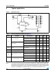
6 Typical application
Note: The external components proposal should be considered as a design reference guide.The
performances mentioned in the electrical characteristics table are not guaranteed for all the
possible electrical parameters of the components included in this list. On an other hand the
operation of STLD40D is not limited with the use of components included in this list.
Figure 3. Application circuit
Table 6. External component proposal (see Figure 3)
Symbol Parameter Test conditions Min. Typ. Max. Unit
D
Boost schottky diode
VRRM 40 V
V
F
at I
F
= 300 mA, T
J
= 25 °C 0.5 V
I
R
at V
R
= 10 V, T
J
= 25 °C 30 µA
STPS1L40M
VRRM 40 V
V
F
at I
F
= 1 A, T
J
= 25 °C 0.46 V
I
R
at V
R
= 20 V, T
J
= 25 °C 21 µA
R
LED
Feedback LED current regulation
resistor
I
LED
= 20 mA 8 Ω
R
SET
Current peak setting resistor I
PEAK
= 0.2 A to 1 A 12 100 kΩ
C
I
Input filtering capacitor Ceramic Type 2.2 µF
C
O
Output capacitance: ceramic low
ESR
Capacitance 4.7 µF
Voltage 35 V
ESR 1.6 Ω
L Boost inductor (height < 2 mm)
Inductance 4.7 µH
DCR 1 Ω
I
SATRSET
= GND 1 A