
Datasheet
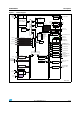

Functional overview STM32F050xx
20/97 Doc ID 023683 Rev 1
3.11.5 SysTick timer
This timer is dedicated to real-time operating systems, but could also be used as a standard
down counter. It features:
● A 24-bit down counter
● Autoreload capability
● Maskable system interrupt generation when the counter reaches 0.
● Programmable clock source (HCLK or HCLK/8)
3.12 Real-time clock (RTC) and backup registers
The RTC and the 5 backup registers are supplied through a switch that takes power either
on V
DD
supply when present or through the V
BAT
pin. The backup registers are five 32-bit
registers used to store 20 bytes of user application data when V
DD
power is not present.
They are not reset by a system or power reset, or when the device wakes up from Standby
mode.
The RTC is an independent BCD timer/counter. Its main features are the following:
● Calendar with subsecond, seconds, minutes, hours (12 or 24 format), week day, date,
month, year, in BCD (binary-coded decimal) format.
● Automatically correction for 28, 29 (leap year), 30, and 31 day of the month.
● Programmable alarm with wake up from Stop and Standby mode capability.
● On-the-fly correction from 1 to 32767 RTC clock pulses. This can be used to
synchronize it with a master clock.
● Digital calibration circuit with 1 ppm resolution, to compensate for quartz crystal
inaccuracy.
● 2 anti-tamper detection pins with programmable filter. The MCU can be woken up from
Stop and Standby modes on tamper event detection.
● Timestamp feature which can be used to save the calendar content. This function can
triggered by an event on the timestamp pin, or by a tamper event. The MCU can be
woken up from Stop and Standby modes on timestamp event detection.
The RTC clock sources can be:
● A 32.768 kHz external crystal
● A resonator or oscillator
● The internal low-power RC oscillator (typical frequency of 40 kHz)
● The high-speed external clock divided by 32.