
Datasheet

STM32F051x Functional overview
Doc ID 022265 Rev 3 13/105
3.4 Cyclic redundancy check calculation unit (CRC)
The CRC (cyclic redundancy check) calculation unit is used to get a CRC code from a 32-bit
data word and a CRC-32 (Ethernet) polynomial.
Among other applications, CRC-based techniques are used to verify data transmission or
storage integrity. In the scope of the EN/IEC 60335-1 standard, they offer a means of
verifying the Flash memory integrity. The CRC calculation unit helps compute a signature of
the software during runtime, to be compared with a reference signature generated at link-
time and stored at a given memory location.
3.5 Power management
3.5.1 Power supply schemes
● V
DD
= 2.0 to 3.6 V: external power supply for I/Os and the internal regulator.
Provided externally through V
DD
pins.
● V
DDA
= 2.0 to 3.6 V: external analog power supply for ADC, Reset blocks, RCs and PLL
(minimum voltage to be applied to V
DDA
is 2.4 V when the ADC and DAC are used).
The V
DDA
voltage level must be always greater or equal to the V
DD
voltage level and
must be provided first.
● V
BAT
= 1.65 to 3.6 V: power supply for RTC, external clock 32 kHz oscillator and backup
registers (through power switch) when V
DD
is not present.
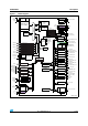
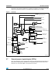
For more details on how to connect power pins, refer to Figure 10: Power supply scheme.
3.5.2 Power supply supervisors
The device has integrated power-on reset (POR) and power-down reset (PDR) circuits.
They are always active, and ensure proper operation above a threshold of 2 V. The device
remains in reset mode when the monitored supply voltage is below a specified threshold,
V
POR/PDR
, without the need for an external reset circuit.
● The POR monitors only the V
DD
supply voltage. During the startup phase it is required
that V
DDA
should arrive first and be greater than or equal to V
DD
.
● The PDR monitors both the V
DD
and V
DDA
supply voltages, however the V
DDA
power
supply supervisor can be disabled (by programming a dedicated Option bit) to reduce
the power consumption if the application design ensures that V
DDA
is higher than or
equal to V
DD
.
The device features an embedded programmable voltage detector (PVD) that monitors the
V
DD
power supply and compares it to the V
PVD
threshold. An interrupt can be generated
when V
DD
drops below the V
PVD
threshold and/or when V
DD
is higher than the V
PVD
threshold. The interrupt service routine can then generate a warning message and/or put
the MCU into a safe state. The PVD is enabled by software.