STM32F051x4 STM32F051x6 STM32F051x8 Low- and medium-density advanced ARM™-based 32-bit MCU with 16 to 64 Kbytes Flash, timers, ADC, DAC and comm. interfaces Datasheet − production data Features ■ Core: ARM 32-bit Cortex™-M0 CPU, frequency up to 48 MHz ■ Memories – 16 to 64 Kbytes of Flash memory – 8 Kbytes of SRAM with HW parity checking ■ CRC calculation unit ■ Reset and power management – Voltage range: 2.0 V to 3.
Contents STM32F051x Contents 1 Introduction . . . . . . . . . . . . . . . . . . . . . . . . . . . . . . . . . . . . . . . . . . . . . . . . 8 2 Description . . . . . . . . . . . . . . . . . . . . . . . . . . . . . . . . . . . . . . . . . . . . . . . . . 9 3 Functional overview . . . . . . . . . . . . . . . . . . . . . . . . . . . . . . . . . . . . . . . . 12 3.1 ARM® CortexTM-M0 core with embedded Flash and SRAM . . . . . . . . . 12 3.2 Memories . . . . . . . . . . . . . . . . . . . . . . . . . .
STM32F051x Contents 3.14.6 SysTick timer . . . . . . . . . . . . . . . . . . . . . . . . . . . . . . . . . . . . . . . . . . . . . 22 3.15 Real-time clock (RTC) and backup registers . . . . . . . . . . . . . . . . . . . . . . 22 3.16 Inter-integrated circuit interfaces (I2C) . . . . . . . . . . . . . . . . . . . . . . . . . . . 23 3.17 Universal synchronous/asynchronous receiver transmitters (USART) . . . 24 3.18 Serial peripheral interface (SPI)/Inter-integrated sound interfaces (I2S) . 24 3.
Contents 7 STM32F051x 6.3.14 NRST pin characteristics . . . . . . . . . . . . . . . . . . . . . . . . . . . . . . . . . . . . 75 6.3.15 12-bit ADC characteristics . . . . . . . . . . . . . . . . . . . . . . . . . . . . . . . . . . . 76 6.3.16 DAC electrical specifications . . . . . . . . . . . . . . . . . . . . . . . . . . . . . . . . . 79 6.3.17 Comparator characteristics . . . . . . . . . . . . . . . . . . . . . . . . . . . . . . . . . . 81 6.3.18 Temperature sensor characteristics . . . . . .
STM32F051x List of tables List of tables Table 1. Table 2. Table 3. Table 4. Table 5. Table 6. Table 7. Table 8. Table 9. Table 10. Table 11. Table 12. Table 13. Table 14. Table 15. Table 16. Table 17. Table 18. Table 19. Table 20. Table 21. Table 22. Table 23. Table 24. Table 25. Table 26. Table 27. Table 28. Table 29. Table 30. Table 31. Table 32. Table 33. Table 34. Table 35. Table 36. Table 37. Table 38. Table 39. Table 40. Table 41. Table 42. Table 43. Table 44. Table 45. Table 46. Table 47.
List of tables Table 48. Table 49. Table 50. Table 51. Table 52. Table 53. Table 54. Table 55. Table 56. Table 57. Table 58. Table 59. Table 60. Table 61. Table 62. Table 63. Table 64. Table 65. Table 66. Table 67. Table 68. Table 69. Table 70. Table 71. Table 72. Table 73. Table 74. 6/105 STM32F051x Electrical sensitivities . . . . . . . . . . . . . . . . . . . . . . . . . . . . . . . . . . . . . . . . . . . . . . . . . . . . . 67 I/O current injection susceptibility . . . . . . . . . . . . . . . . . .
STM32F051x List of figures List of figures Figure 1. Figure 2. Figure 3. Figure 4. Figure 5. Figure 6. Figure 7. Figure 8. Figure 9. Figure 10. Figure 11. Figure 12. Figure 13. Figure 14. Figure 15. Figure 16. Figure 17. Figure 18. Figure 19. Figure 20. Figure 21. Figure 22. Figure 23. Figure 24. Figure 25. Figure 26. Figure 27. Figure 28. Figure 29. Figure 30. Figure 31. Figure 32. Figure 33. Figure 34. Figure 35. Figure 36. Figure 37. Figure 38. Figure 39. Block diagram . . . . . . . . . . . . . . . .
Introduction 1 STM32F051x Introduction This datasheet provides the ordering information and mechanical device characteristics of the STM32F051x microcontrollers. This STM32F051x4, STM32F051x6, and STM32F051x8 datasheet should be read in conjunction with the STM32F0xxxx reference manual (RM0091). The reference manual is available from the STMicroelectronics website www.st.com. For information on the ARM Cortex™-M0 core, please refer to the Cortex™-M0 Technical Reference Manual, available from the www.arm.
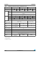
STM32F051x 2 Description Description The STM32F051x family incorporates the high-performance ARM Cortex™-M0 32-bit RISC core operating at a 48 MHz frequency, high-speed embedded memories (Flash memory up to 64 Kbytes and SRAM up to 8 Kbytes), and an extensive range of enhanced peripherals and I/Os.
Description Table 2. STM32F051x STM32F051x family device features and peripheral counts Peripheral STM32F051Kx Flash (Kbytes) 16 SRAM (Kbytes) Timers 32 STM32F051Cx 64 4 16 32 8 Advanced control 1 (16-bit) General purpose 5 (16-bit) 1 (32-bit) 16 32 1[1] SPI [I2S] I2C USART (2) 1[1] (2) 1(3) 1(4) 1(3) 1(4) 2 2 CEC 8 4 8 2[1] 1[1] (2) 2[1] 2 1(3) 2 1(4) 2 1 12-bit synchronized ADC (number of channels) 1 (10 ext. + 3 int.) 1 (16 ext. + 3 int.
STM32F051x 3ERIAL 7IRE $EBUG 6$$ FLASH OBL )NTERFACE 37#,+ 37$!4 AS !& Block diagram .6)# '0 $-! CHANNELS "US-ATRIX .6)# 32!- #/24%8 - #05 F(#,+ -(Z CONTROLLER Figure 1. Description 0/7%2 6/,4 2%' 6 4/ 6 &,!3( +" BITS 6$$ TO 6 633 6$$ 0/2 2ESET 32! +" 6$$! )NT 3500,9 350%26)3)/. 0/2 0$2 6 $$ 06$ 2# (3 -(Z 2# (3 -(Z .234 6$$! 6$$! 6$$ 2# ,3 84!, /3# -(Z 0,, /3#?).
Functional overview STM32F051x 3 Functional overview 3.1 ARM® CortexTM-M0 core with embedded Flash and SRAM The ARM Cortex™-M0 processor is the latest generation of ARM processors for embedded systems. It has been developed to provide a low-cost platform that meets the needs of MCU implementation, with a reduced pin count and low-power consumption, while delivering outstanding computational performance and an advanced system response to interrupts.
STM32F051x 3.4 Functional overview Cyclic redundancy check calculation unit (CRC) The CRC (cyclic redundancy check) calculation unit is used to get a CRC code from a 32-bit data word and a CRC-32 (Ethernet) polynomial. Among other applications, CRC-based techniques are used to verify data transmission or storage integrity. In the scope of the EN/IEC 60335-1 standard, they offer a means of verifying the Flash memory integrity.
Functional overview 3.5.3 STM32F051x Voltage regulator The regulator has three operating modes: main (MR), low power (LPR) and power down. ● MR is used in normal operating mode (Run) ● LPR can be used in Stop mode where the power demand is reduced ● Power down is used in Standby mode: the regulator output is in high impedance: the kernel circuitry is powered down, inducing zero consumption (but the contents of the registers and SRAM are lost) This regulator is always enabled after reset.
STM32F051x Functional overview Several prescalers allow the application to configure the frequency of the AHB and the APB domains. The maximum frequency of the AHB and the APB domains is 48 MHz. Figure 2. Clock tree &,)4&#,+ TO &LASH PROGRAMMING INTERFACE (3) TO ) # 393#,+ TO ) 3 ,3% -(Z (3) (3) 2# TO #%# (#,+ 0,,32# 0,,-5, 0,, X X X 37 (3) 0,,#,+ (3% !(" !(" PRESCALER 393#,+ #33 /3#?/54 /3#?). -(Z (3% /3# -(Z (3) (3) 2# /3# ?).
Functional overview STM32F051x The I/O configuration can be locked if needed following a specific sequence in order to avoid spurious writing to the I/Os registers. 3.8 Direct memory access controller (DMA) The 5-channel general-purpose DMAs manage memory-to-memory, peripheral-to-memory and memory-to-peripheral transfers. The DMA supports circular buffer management, removing the need for user code intervention when the controller reaches the end of the buffer.
STM32F051x Functional overview sensor, voltage reference, VBAT voltage measurement) channels and performs conversions in single-shot or scan modes. In scan mode, automatic conversion is performed on a selected group of analog inputs. The ADC can be served by the DMA controller. An analog watchdog feature allows very precise monitoring of the converted voltage of one, some or all selected channels. An interrupt is generated when the converted voltage is outside the programmed thresholds. 3.10.
Functional overview 3.10.3 STM32F051x VBAT battery voltage monitoring This embedded hardware feature allows the application to measure the VBAT battery voltage using the internal ADC channel ADC_IN18. As the VBAT voltage may be higher than VDDA, and thus outside the ADC input range, the VBAT pin is internally connected to a bridge divider by 2. As a consequence, the converted digital value is half the VBAT voltage. 3.
STM32F051x Functional overview components to operate. The STM32F051x devices offer up to 18 capacitive sensing channels distributed over 6 analog I/O groups. Table 5.
Functional overview 3.14 STM32F051x Timers and watchdogs The STM32F051x family devices include up to six general-purpose timers, one basic timer and an advanced control timer. Table 7 compares the features of the advanced-control, general-purpose and basic timers. Table 7.
STM32F051x 3.14.2 Functional overview General-purpose timers (TIM2..3, TIM14..17) There are six synchronizable general-purpose timers embedded in the STM32F051x devices (see Table 7 for differences). Each general-purpose timer can be used to generate PWM outputs, or as simple time base. TIM2, TIM3 STM32F051x devices feature two synchronizable 4-channel general-purpose timers. TIM2 is based on a 32-bit auto-reload up/downcounter and a 16-bit prescaler.
Functional overview STM32F051x operates independently from the main clock, it can operate in Stop and Standby modes. It can be used either as a watchdog to reset the device when a problem occurs, or as a free running timer for application timeout management. It is hardware or software configurable through the option bytes. The counter can be frozen in debug mode. 3.14.5 System window watchdog (WWDG) The system window watchdog is based on a 7-bit downcounter that can be set as free running.
STM32F051x 3.16 Functional overview Inter-integrated circuit interfaces (I2C) Up to two I2C interfaces (I2C1 and I2C2) can operate in multimaster or slave modes. Both can support Standard mode (up to 100 kbit/s) or Fast mode (up to 400 kbit/s) and I2C1 supports also Fast Mode Plus (up to 1 Mbit/s) with 20 mA output drive. Both support 7-bit and 10-bit addressing modes, multiple 7-bit slave addresses (2 addresses, 1 with configurable mask). They also include programmable analog and digital noise filters.
Functional overview 3.17 STM32F051x Universal synchronous/asynchronous receiver transmitters (USART) The device embeds up to two universal synchronous/asynchronous receiver transmitters (USART1 and USART2), which communicate at speeds of up to 6 Mbit/s. They provide hardware management of the CTS, RTS and RS485 DE signals, multiprocessor communication mode, master synchronous communication and single-wire half-duplex communication mode.
STM32F051x Functional overview programmable linear prescaler. When operating in master mode it can output a clock for an external audio component at 256 times the sampling frequency. Refer to Table 11 for the differences between SPI1 and SPI2. Table 11. STM32F051x SPI/I2S implementation SPI features(1) SPI1 SPI2 Hardware CRC calculation X X Rx/Tx FIFO X X NSS pulse mode X X I2S mode X TI mode X X 1. X = supported. 3.
Pinouts and pin description Pinouts and pin description 6"!4 0# 0# /3# ?). ,1&0 0! 0& 0& 0# /3# ?/54 0& /3#?). 0& /3#?/54 .234 0# 0# 0# 0# 633! 6$$! 0! 0! 0! 0" 0" "//4 0" 0" 0" 0" 0" 0$ 0# 0# 0# 0! 0! LQFP64 64-pin package pinout 6$$ 633 Figure 3.
STM32F051x 6"!4 0# 0# /3# ?). 0# /3# ?/54 0& /3#?). 0& /3#?/54 .234 633! 6$$! 0! 0! 0! 0" 0! 0" 0" 0" 0" 0" "//4 0" LQFP48 48-pin package pinout 6$$ 633 0& 0& 0! 0! 0! 0! 0! 0! 0" 0" 0" 0" 6$$ 0" 633 0" 0" 0" 0" 0! 0! 0! 0! ,1&0 0! 0! Figure 4.
Pinouts and pin description UFQFPN32 32-pin package pinout 0" "//4 0" 0" 0" 0" 0" 0! Figure 6. STM32F051x 633 633! 0! 0! 0! 0! 0! 0! 0! 6$$ 0! 0! 0! 0! 0! 0" 0" 0" 6$$ 0& /3#?). 0& /3#?/54 .234 6$$! 0! 0! 0! -3 6 Table 12.
STM32F051x Pin definitions LQFP48 LQFP32 UFQFPN32 Pin functions LQFP64 Pin type Pin number I/O structure Table 13.
Pinouts and pin description Pin definitions (continued) Pin name (function after reset) Pin type UFQFPN32 LQFP32 LQFP48 LQFP64 Pin number I/O structure Table 13.
STM32F051x Table 13.
Pinouts and pin description Table 13.
Pin name Alternate functions selected through GPIOA_AFR registers for port A AF0 PA0 AF1 AF2 AF3 USART2_CTS TIM2_CH1_ ETR TSC_G1_IO1 AF4 AF5 AF6 AF7 COMP1_OUT Doc ID 022265 Rev 3 PA1 EVENTOUT USART2_RTS TIM2_CH2 TSC_G1_IO2 PA2 TIM15_CH1 USART2_TX TIM2_CH3 TSC_G1_IO3 PA3 TIM15_CH2 USART2_RX TIM2_CH4 TSC_G1_IO4 PA4 SPI1_NSS/ I2S1_WS USART2_CK PA5 SPI1_SCK/ I2S1_CK CEC TIM2_CH1_ ETR TSC_G2_IO2 PA6 SPI1_MISO/ I2S1_MCK TIM3_CH1 TIM1_BKIN TSC_G2_IO3 PA7 SPI1_MOSI/ I2S1_S
Alternate functions selected through GPIOA_AFR registers for port B Pin name AF0 AF1 AF2 AF3 PB0 EVENTOUT TIM3_CH3 TIM1_CH2N TSC_G3_IO2 PB1 TIM14_CH1 TIM3_CH4 TIM1_CH3N TSC_G3_IO3 PB2 TSC_G3_IO4 Doc ID 022265 Rev 3 PB3 SPI1_SCK / I2S1_CK EVENTOUT TIM2_CH2 TSC_G5_IO1 PB4 SPI1_MISO / I2S1_MCK TIM3_CH1 EVENTOUT TSC_G5_IO2 PB5 SPI1_MOSI / I2S1_SD TIM3_CH2 TIM16_BKIN I2C1_SMBA PB6 USART1_TX I2C1_SCL TIM16_CH1N TSC_G5_IO3 PB7 USART1_RX I2C1_SDA TIM17_CH1N TSC_G5_IO4 PB8
STM32F051x 5 Memory mapping Memory mapping Figure 7.
Memory mapping STM32F051x Table 16.
STM32F051x Memory mapping Table 16.
STM32F051x Electrical characteristics 6 Electrical characteristics 6.1 Parameter conditions Unless otherwise specified, all voltages are referenced to VSS. 6.1.1 Minimum and maximum values Unless otherwise specified, the minimum and maximum values are guaranteed in the worst conditions of ambient temperature, supply voltage and frequencies by tests in production on 100% of the devices with an ambient temperature at TA = 25 °C and TA = TAmax (given by the selected temperature range).
Electrical characteristics 6.1.6 STM32F051x Power supply scheme Figure 10. Power supply scheme 6"!4 "ACKUP CIRCUITRY ,3% 24# 7AKE UP LOGIC "ACKUP REGISTERS /54 '0 ) /S ). ,EVEL SHIFTER 0O WER SWI TCH 6 )/ ,OGIC +ERNEL LOGIC #05 $IGITAL -EMORIES 6$$ § 6$$ § N& § & 6$$! 2EGULATOR § 633 6$$! 62%& 62%& N& & !$# $!# !NALOG 2#S 0,, 633! -3 6 Caution: Each power supply pair (VDD/VSS, VDDA/VSSA etc..
STM32F051x 6.2 Electrical characteristics Absolute maximum ratings Stresses above the absolute maximum ratings listed in Table 17: Voltage characteristics, Table 18: Current characteristics, and Table 19: Thermal characteristics may cause permanent damage to the device. These are stress ratings only and functional operation of the device at these conditions is not implied. Exposure to maximum rating conditions for extended periods may affect device reliability. Table 17.
Electrical characteristics Table 18. STM32F051x Current characteristics Symbol Ratings Max.
STM32F051x Electrical characteristics 6.3 Operating conditions 6.3.1 General operating conditions Table 20. General operating conditions Symbol Parameter fHCLK Min Max Internal AHB clock frequency 0 48 fPCLK Internal APB clock frequency 0 48 VDD Standard operating voltage 2 3.6 2 3.6 2.4 3.6 1.65 3.
Electrical characteristics 6.3.2 STM32F051x Operating conditions at power-up / power-down The parameters given in Table 21 are derived from tests performed under the ambient temperature condition summarized in Table 20. Table 21. Operating conditions at power-up / power-down Symbol Parameter tVDD tVDDA 6.3.
STM32F051x Electrical characteristics Table 23. Symbol Programmable voltage detector characteristics (continued) Parameter Min(1) Typ Max(1) Unit Rising edge 2.57 2.68 2.79 V Falling edge 2.47 2.58 2.69 V Rising edge 2.66 2.78 2.9 V Falling edge 2.56 2.68 2.8 V Rising edge 2.76 2.88 3 V Falling edge 2.66 2.78 2.
Electrical characteristics STM32F051x Typical and maximum current consumption The MCU is placed under the following conditions: ● All I/O pins are in input mode with a static value at VDD or VSS (no load) ● All peripherals are disabled except when explicitly mentioned ● The Flash memory access time is adjusted to the fHCLK frequency (0 wait state from 0 to 24 MHz and 1 wait state above 24 MHz) ● Prefetch is ON when the peripherals are enabled, otherwise it is OFF (to enable prefetch the PRFTBE bit
STM32F051x Table 25. Electrical characteristics Typical and maximum current consumption from VDD supply at VDD = 3.
Electrical characteristics Table 26. STM32F051x Typical and maximum current consumption from the VDDA supply VDDA = 2.4 V Symbol Parameter Conditions (1) VDDA = 3.
STM32F051x Table 27. Typical and maximum VDD consumption in Stop and Standby modes Symbol Parameter IDD Electrical characteristics Max(1) 2.0 V 2.4 V 2.7 V 3.0 V 3.3 V 3.6 V TA = TA = TA = 25 °C 85 °C 105 °C Conditions Regulator in run mode, all oscillators OFF Supply current in Regulator in low-power Stop mode mode, all oscillators OFF Supply current in Standby mode Typ @VDD (VDD = VDDA) 15 15.1 15.25 15.45 15.7 3.15 3.25 3.35 3.45 3.
Electrical characteristics Table 28. STM32F051x Typical and maximum VDDA consumption in Stop and Standby modes Supply current in Stop mode Supply current in Standby mode Supply current in Standby mode VDDA monitoring OFF IDDA Supply current in Stop mode Max(1) 2.0 V 2.4 V 2.7 V 3.0 V 3.3 V 3.6 V TA = TA = TA = 25 °C 85 °C 105 °C Conditions VDDA monitoring ON Symbol Parameter Typ @VDD (VDD = VDDA) Regulator in run mode, 1.85 all oscillators OFF 2 2.15 2.3 2.45 2.6 3.5 3.5 4.
STM32F051x Electrical characteristics Typical current consumption The MCU is placed under the following conditions: ● VDD=VDDA=3.
Electrical characteristics Table 31. STM32F051x Typical current consumption in Sleep mode, code running from Flash or RAM Typ Symbol IDD Parameter Conditions Supply current in Sleep mode from VDD supply Running from HSE crystal clock 8 MHz, code executing from Flash or RAM IDDA 52/105 Supply current in Sleep mode from VDDA supply fHCLK Peripherals Peripherals enabled disabled 48 MHz 13.9 2.98 36 MHz 10.55 2.84 32 MHz 9.6 2.6 24 MHz 7.23 2.09 16 MHz 5.01 1.58 8 MHz 2.68 0.
STM32F051x Electrical characteristics I/O system current consumption The current consumption of the I/O system has two components: static and dynamic. I/O static current consumption All the I/Os used as inputs with pull-up generate current consumption when the pin is externally held low. The value of this current consumption can be simply computed by using the pull-up/pull-down resistors values given in Table 50: I/O static characteristics.
Electrical characteristics Table 32. Symbol STM32F051x Switching output I/O current consumption Parameter Conditions(1) VDD = 3.3 V C =CINT VDD = 3.3 Volts CEXT = 0 pF C = CINT + CEXT+ CS VDD = 3.3 Volts CEXT = 10 pF C = CINT + CEXT+ CS ISW I/O current consumption VDD = 3.3 Volts CEXT = 22 pF C = CINT + CEXT+ CS VDD = 3.3 Volts CEXT = 33 pF C = CINT + CEXT+ CS VDD = 3.3 Volts CEXT = 47 pF C = CINT + CEXT+ CS C = Cint VDD = 2.4 Volts CEXT = 47 pF C = CINT + CEXT+ CS C = Cint 1.
STM32F051x Electrical characteristics On-chip peripheral current consumption The current consumption of the on-chip peripherals is given in Table 33.
Electrical characteristics Table 33. STM32F051x Peripheral current consumption Typical consumption at 25 °C Peripheral Unit IDD IDDA ADC(1) 0.53 0.964 CEC 0.24 - CRC 0.10 - DAC(2) 0.27 0.408 DBGMCU 0.18 - DMA 0.35 - GPIOA 0.48 - GPIOB 0.58 - GPIOC 0.12 - GPIOD 0.04 - GPIOF 0.06 - I2C1 0.43 - I2C2 0.42 - PWR 0.22 - SPI1/I2S1 0.63 - SPI2 0.53 - SYSCFG & COMP 0.28 See note (3) TIM1 1.01 - TIM2 1.00 - TIM3 0.78 - TIM6 0.32 - TIM14 0.
STM32F051x 6.3.6 Electrical characteristics External clock source characteristics High-speed external user clock generated from an external source In bypass mode the HSE oscillator is switched off and the input pin is a standard GPIO. The external clock signal has to respect the I/O characteristics in Section 6.3.13. However, the recommended clock input waveform is shown in Figure 12. Table 34.
Electrical characteristics STM32F051x Low-speed external user clock generated from an external source In bypass mode the LSE oscillator is switched off and the input pin is a standard GPIO. The external clock signal has to respect the I/O characteristics in Section 6.3.13. However, the recommended clock input waveform is shown in Figure 13. Table 35. Low-speed external user clock characteristics Parameter(1) Symbol Conditions Min Typ Max Unit - 32.
STM32F051x Electrical characteristics High-speed external clock generated from a crystal/ceramic resonator The high-speed external (HSE) clock can be supplied with a 4 to 32 MHz crystal/ceramic resonator oscillator. All the information given in this paragraph are based on design simulation results obtained with typical external components specified in Table 36.
Electrical characteristics STM32F051x Figure 14. Typical application with an 8 MHz crystal 2ESONATOR WITH INTEGRATED CAPACITORS #, F(3% /3#?). -( Z RESONATOR #, 2%84 2& "IAS CONTROLLED GAIN /3#?/5 4 -3 6 1. REXT value depends on the crystal characteristics.
STM32F051x Electrical characteristics Low-speed external clock generated from a crystal resonator The low-speed external (LSE) clock can be supplied with a 32.768 kHz crystal resonator oscillator. All the information given in this paragraph are based on design simulation results obtained with typical external components specified in Table 37.
Electrical characteristics STM32F051x Figure 15. Typical application with a 32.768 kHz crystal 2ESONATOR WITH INTEGRATED CAPACITORS #, F,3% /3# ?). $RIVE PROGRAMMABLE AMPLIFIER K( Z RESONATOR /3# ?/5 4 #, -3 Note: An external resistor is not required between OSC32_IN and OSC32_OUT and it is forbidden to add one. 6.3.
STM32F051x Electrical characteristics High-speed internal 14 MHz (HSI14) RC oscillator (dedicated to ADC) Table 39.
Electrical characteristics Table 41. STM32F051x Low-power mode wakeup timings Typ @VDD Symbol tWUSTOP Parameter Wakeup from Stop mode Conditions Max Unit = 2.0 V = 2.4 V = 2.7 V =3V = 3.3 V Regulator in run mode 4.2 4.2 4.2 4.2 4.2 5 Regulator in low power mode 8.05 7.05 6.6 6.27 6.05 9 µs tWUSTANDBY Wakeup from Standby mode tWUSLEEP 6.3.8 Wakeup from Sleep mode 60.35 55.6 53.5 52.02 50.96 1.1 1.1 1.1 1.1 1.
STM32F051x Electrical characteristics Table 43. Flash memory characteristics Min Typ Max(1) Unit 16-bit programming time TA = –40 to +105 °C 40 53.5 60 µs Page (1 KB) erase time TA = –40 to +105 °C 20 - 40 ms tME Mass erase time TA = –40 to +105 °C 20 - 40 ms Write mode - - 10 mA IDD Supply current Erase mode - - 12 mA 2 - 3.6 V Symbol tprog tERASE Vprog Parameter Conditions Programming voltage 1. Guaranteed by design, not tested in production. Table 44.
Electrical characteristics 6.3.10 STM32F051x EMC characteristics Susceptibility tests are performed on a sample basis during device characterization. Functional EMS (electromagnetic susceptibility) While a simple application is executed on the device (toggling 2 LEDs through I/O ports). the device is stressed by two electromagnetic events until a failure occurs.
STM32F051x Electrical characteristics Prequalification trials Most of the common failures (unexpected reset and program counter corruption) can be reproduced by manually forcing a low state on the NRST pin or the Oscillator pins for 1 second. To complete these trials, ESD stress can be applied directly on the device, over the range of specification values. When unexpected behavior is detected, the software can be hardened to prevent unrecoverable errors occurring (see application note AN1015).
Electrical characteristics STM32F051x Static latch-up Two complementary static tests are required on six parts to assess the latch-up performance: ● A supply overvoltage is applied to each power supply pin ● A current injection is applied to each input, output and configurable I/O pin These tests are compliant with EIA/JESD 78A IC latch-up standard. Table 48. Symbol LU 6.3.
STM32F051x 6.3.13 Electrical characteristics I/O port characteristics General input/output characteristics Unless otherwise specified, the parameters given in Table 50 are derived from tests performed under the conditions summarized in Table 20. All I/Os are CMOS and TTL compliant. Table 50. Symbol VIL I/O static characteristics Parameter Conditions Min Typ Max Standard I/O input low level voltage –0.3 - 0.3VDD+0.07 TTa I/O input low level voltage –0.3 - 0.3VDD+0.
Electrical characteristics Table 50. Symbol Ilkg STM32F051x I/O static characteristics (continued) Parameter Input leakage current Conditions Min Typ Max VSS ≤ VIN ≤ VDD I/O TC, FT and FTf - - ±0.1 VSS ≤ VIN ≤ VDD 2 V≤ VDD ≤ VDDA ≤ 3.6 V I/O TTa used in digital mode - - ±0.1 VIN= 5 V I/O FT and FTf - - 10 (3) Unit µA VIN= 3.6 V, 2 V≤ VDD ≤ VIN VDDA = 3.6 V I/O TTa used in digital mode - - 1 VSS ≤ VIN ≤ VDDA 2 V≤ VDD ≤ VDDA ≤ 3.6 V I/O TTa used in analog mode - - ±0.
STM32F051x Electrical characteristics Figure 16. TC and TTa I/O input characteristics - CMOS port VIL/VIH (V) V DD ard tand Ss CMO VIHmin 2.0 nts eme V IHmin = 0.7 ir requ 98 +0.3 45V DD V IHmin = 0.4 0.07 V DD+ = 0.3 V ILmax 1.3 Input range not guaranteed CMOS standard requirements VILmax = 0.3VDD VILmax 0.7 0.6 VDD (V) 2.0 2.7 3.0 3.3 3.6 MS30255V1 Figure 17. TC and TTa I/O input characteristics - TTL port VIL/VIH (V) 98 +0.3 45V DD = 0.
Electrical characteristics STM32F051x Figure 18. Five volt tolerant (FT and FTf) I/O input characteristics - CMOS port VIL/VIH (V) CMOS standard requirements VIH min= 0.7VDD 2.0 = 0.5 -0.2 75V DD Input range not guaranteed 1.0 0.2 V DD+ V IHmin = 0.4 V ILmax CMOS standard requirements VILmax = 0.3VDD 0.5 VDD (V) 2.0 3.6 MS30257V1 Figure 19. Five volt tolerant (FT and FTf) I/O input characteristics - TTL port VIL/VIH (V) TTL standard requirements VIHmin = 2 V 2.
STM32F051x Electrical characteristics Output driving current The GPIOs (general purpose input/outputs) can sink or source up to +/-8 mA, and sink or source up to +/- 20 mA (with a relaxed VOL/VOH). In the user application, the number of I/O pins which can drive current must be limited to respect the absolute maximum rating specified in Section 6.
Electrical characteristics STM32F051x Input/output AC characteristics The definition and values of input/output AC characteristics are given in Figure 20 and Table 52, respectively. Unless otherwise specified, the parameters given are derived from tests performed under ambient temperature and VDD supply voltage conditions summarized in Table 20. Table 52.
STM32F051x Electrical characteristics Figure 20.
Electrical characteristics 6.3.14 STM32F051x NRST pin characteristics The NRST pin input driver uses CMOS technology. It is connected to a permanent pull-up resistor, RPU (see Table 50). Unless otherwise specified, the parameters given in Table 53 are derived from tests performed under ambient temperature and VDD supply voltage conditions summarized in Table 20. Table 53. NRST pin characteristics Symbol Parameter Conditions VIL(NRST)(1) NRST Input low level voltage Min Typ Max –0.3 - 0.
STM32F051x 6.3.15 Electrical characteristics 12-bit ADC characteristics Unless otherwise specified, the parameters given in Table 54 are preliminary values derived from tests performed under ambient temperature, fPCLK2 frequency and VDDA supply voltage conditions summarized in Table 20. Note: It is recommended to perform a calibration after each power-up. Table 54. ADC characteristics Symbol Parameter Conditions Min Typ Max Unit VDDA Analog supply voltage for ADC ON 2.4 - 3.
Electrical characteristics STM32F051x Equation 1: RAIN max formula TS - – R ADC R AIN < ------------------------------------------------------------N+2 f ADC × C ADC × ln ( 2 ) The formula above (Equation 1) is used to determine the maximum external impedance allowed for an error below 1/4 of LSB. Here N = 12 (from 12-bit resolution). Table 55. RAIN max for fADC = 14 MHz(1) Ts (cycles) tS (µs) RAIN max (kΩ) 1.5 0.11 0.4 7.5 0.54 5.9 13.5 0.96 11.4 28.5 2.04 25.2 41.5 2.96 37.2 55.5 3.
STM32F051x Electrical characteristics 2. ADC Accuracy vs. Negative Injection Current: Injecting negative current on any of the standard (nonrobust) analog input pins should be avoided as this significantly reduces the accuracy of the conversion being performed on another analog input. It is recommended to add a Schottky diode (pin to ground) to standard analog pins which may potentially inject negative current.
Electrical characteristics STM32F051x 6.3.16 DAC electrical specifications Table 57. DAC characteristics Symbol Parameter Min Typ Max Unit 2.4 - 3.6 V 5 - - Comments VDDA Analog supply voltage for DAC ON RLOAD(1) Resistive load with buffer ON RO(1) Impedance output with buffer OFF - - 15 When the buffer is OFF, the Minimum resistive load between DAC_OUT kΩ and VSS to have a 1% accuracy is 1.
STM32F051x Table 57.
Electrical characteristics STM32F051x 6.3.17 Comparator characteristics Table 58. Comparator characteristics Symbol VDDA Parameter Conditions Min Typ Max(1) Unit Analog supply voltage 2 - 3.6 VIN Comparator input voltage range 0 - VDDA V VBG Scaler input voltage - 1.2 VSC Scaler offset voltage - ±5 ±10 mV tS_SC Scaler startup time from power down - - 0.
STM32F051x Table 58.
Electrical characteristics 6.3.18 STM32F051x Temperature sensor characteristics Table 59. TS characteristics Symbol Parameter Min Typ Max Unit - ±1 ±2 °C Average slope 4.0 4.3 4.6 mV/°C V25 Voltage at 25 °C 1.34 1.43 1.52 V tSTART(1) Startup time 4 - 10 µs TS_temp(1)(2) ADC sampling time when reading the temperature 17.1 - - µs TL(1) VSENSE linearity with temperature Avg_Slope (1) 1. Guaranteed by design, not tested in production. 2.
STM32F051x Electrical characteristics Table 61. TIMx(1) characteristics (continued) Symbol Parameter tCOUNTER 16-bit counter clock period tMAX_COUNT Conditions fTIMxCLK = 48 MHz Maximum possible count with 32-bit counter fTIMxCLK = 48 MHz Min Max Unit 1 65536 tTIMxCLK 0.0208 1365 µs - 65536 × 65536 tTIMxCLK - 89.48 s 1. TIMx is used as a general term to refer to the TIM1, TIM2, TIM3, TIM6, TIM14, TIM15, TIM16 and TIM17 timers. Table 62.
Electrical characteristics 6.3.21 STM32F051x Communication interfaces I2C interface characteristics Unless otherwise specified, the parameters given in Table 64 are derived from tests performed under ambient temperature, fPCLK frequency and VDD supply voltage conditions summarized in Table 20. The I2C interface meets the requirements of the standard I2C communication protocol with the following restrictions: the I/O pins SDA and SCL are mapped to are not “true” opendrain.
STM32F051x Electrical characteristics Table 65. I2C analog filter characteristics(1) Symbol tSP Parameter Min Max Unit 50 260 ns Pulse width of spikes that are suppressed by the analog filter 1. Guaranteed by design, not tested in production. Figure 25.
Electrical characteristics Table 66.
STM32F051x Electrical characteristics Figure 27. SPI timing diagram - slave mode and CPHA = 1(1) NSS input tSU(NSS) SCK Input CPHA=1 CPOL=0 CPHA=1 CPOL=1 tc(SCK) th(NSS) tw(SCKH) tw(SCKL) tv(SO) ta(SO) MISO OUT P UT th(SO) MS B O UT tsu(SI) MOSI I NPUT BI T6 OUT tr(SCK) tf(SCK) tdis(SO) LSB OUT th(SI) M SB IN B I T1 IN LSB IN ai14135 1. Measurement points are done at CMOS levels: 0.3VDD and 0.7VDD. Figure 28.
Electrical characteristics STM32F051x I2S characteristics Table 67. Symbol fCK 1/tc(CK) Parameter I2S clock frequency Conditions Master mode (data: 16 bits, Audio frequency = 48 kHz) Slave mode 2 I S clock rise time tr(CK) 2 I S clock fall time tf(CK) tw(CKH) (1) I2S clock high time Capacitive load CL = 15 pF Min Max 1.597 1.601 MHz 0 6.
STM32F051x Electrical characteristics Figure 29. I2S slave timing diagram (Philips protocol) CK Input tc(CK) CPOL = 0 CPOL = 1 tw(CKH) th(WS) tw(CKL) WS input tv(SD_ST) tsu(WS) SDtransmit LSB transmit(2) MSB transmit Bitn transmit tsu(SD_SR) LSB receive(2) SDreceive th(SD_ST) LSB transmit th(SD_SR) MSB receive Bitn receive LSB receive ai14881b 1. Measurement points are done at CMOS levels: 0.3 × VDD and 0.7 × VDD. 2. LSB transmit/receive of the previously transmitted byte.
Package characteristics STM32F051x 7 Package characteristics 7.1 Package mechanical data In order to meet environmental requirements, ST offers these devices in different grades of ECOPACK® packages, depending on their level of environmental compliance. ECOPACK® specifications, grade definitions and product status are available at: www.st.com. ECOPACK® is an ST trademark.
STM32F051x Package characteristics Figure 31. LQFP64 – 10 x 10 mm 64 pin low-profile quad flat package outline D ccc C D1 A A2 D3 33 48 32 49 b L1 E3 E1 E A1 L K 64 17 Pin 1 identification 16 1 c 5W_ME 1. Drawing is not to scale. Table 68. LQFP64 – 10 x 10 mm 64 pin low-profile quad flat package mechanical data inches(1) millimeters Symbol Min Typ A Max Min Typ 1.600 A1 0.050 A2 1.350 b 0.170 c 0.090 D 11.800 D1 9.800 D. Max 0.0630 0.150 0.0020 0.0059 1.400 1.
Package characteristics STM32F051x Figure 32. LQFP64 recommended footprint 48 33 0.3 49 12.7 32 0.5 10.3 10.3 64 17 1.2 1 16 7.8 12.7 ai14909 1. Drawing is not to scale. 2. Dimensions are in millimeters.
STM32F051x Package characteristics Figure 33. LQFP48 – 7 x 7mm, 48-pin low-profile quad flat package outline D ccc C D1 D3 A A2 25 36 24 37 L1 b E3 E1 E 48 Pin 1 identification 13 1 L A1 K c 12 5B_ME 1. Drawing is not to scale. Table 69. LQFP48 – 7 x 7mm, 48-pin low-profile quad flat package mechanical data inches(1) millimeters Symbol Min Typ A Max Min Typ 1.600 A1 0.050 A2 1.350 b 0.170 c 0.090 D 8.800 D1 6.800 D3 Max 0.0630 0.150 0.0020 1.400 1.450 0.0531 0.
Package characteristics STM32F051x Figure 34. LQFP48 recommended footprint 0.50 1.20 9.70 0.30 25 36 37 24 0.20 7.30 5.80 7.30 48 13 12 1 1.20 5.80 9.70 ai14911b 1. Drawing is not to scale. 2. Dimensions are in millimeters.
STM32F051x Package characteristics Figure 35. LQFP32 7 x 7mm 32-pin low-profile quad flat package outline CCC # $ $ $ ! ! , B % % % 0IN IDENTIFICATION ! , + C 6?-% 1. Drawing is not to scale. Table 70. LQFP32 7 x 7mm 32-pin low-profile quad flat package mechanical data inches(1) millimeters Symbol Min Typ A Max Min Typ 1.600 A1 0.050 A2 1.350 b 0.300 c 0.090 D 8.800 D1 6.800 D3 Max 0.0630 0.150 0.0020 1.400 1.450 0.0531 0.0551 0.
Package characteristics STM32F051x Figure 36. LQFP32 recommended footprint 6?&0 1. Drawing is not to scale. 2. Dimensions are expressed in millimeters.
STM32F051x Package characteristics Figure 37. UFQFPN32 - 32-lead ultra thin fine pitch quad flat no-lead package outline (5 x 5) Seating plane C ddd C A A1 A3 D e 16 9 17 8 E2 E b 24 1 L 32 Pin # 1 ID R = 0.30 D2 L Bottom view A0B8_ME 1. Drawing is not to scale. 2. All leads/pads should also be soldered to the PCB to improve the lead/pad solder joint life. 3. There is an exposed die pad on the underside of the UFQFPN package.
Package characteristics STM32F051x Figure 38. UFQFPN32 recommended footprint 1. Drawing is not to scale. 2. Dimensions are expressed in millimeters. 7.2 Thermal characteristics The maximum chip junction temperature (TJmax) must never exceed the values given in Table 20: General operating conditions.
STM32F051x Package characteristics Table 72. Package thermal characteristics Symbol ΘJA 7.2.1 Parameter Value Thermal resistance junction-ambient LQFP64 - 10 × 10 mm / 0.5 mm pitch 45 Thermal resistance junction-ambient LQFP48 - 7 × 7 mm 55 Thermal resistance junction-ambient LQFP32 - 7 × 7 mm 56 Thermal resistance junction-ambient UFQFPN32 - 5 × 5 mm 38 Unit °C/W Reference document JESD51-2 Integrated Circuits Thermal Test Method Environment Conditions - Natural Convection (Still Air).
Package characteristics Note: STM32F051x With this given PDmax we can find the TAmax allowed for a given device temperature range (order code suffix 6 or 7). Suffix 6: TAmax = TJmax - (45°C/W × 447 mW) = 105-20.115 = 84.885 °C Suffix 7: TAmax = TJmax - (45°C/W × 447 mW) = 125-20.115 = 104.
STM32F051x 8 Part numbering Part numbering For a list of available options (memory, package, and so on) or for further information on any aspect of this device, please contact your nearest ST sales office. Table 73.
STM32F051x 9 Revision history Revision history Table 74. Document revision history Date Revision 05-Apr-2012 1 Initial release 2 Updated Table 2: STM32F051x family device features and peripheral counts for 1 SPI and 1 I2C in 32-pin package Corrected Group 3 pin order in Table 5: Capacitive sensing GPIOs available on STM32F051x devices. Updated current consumptionTable 25 to Table 29.
STM32F051x Please Read Carefully: Information in this document is provided solely in connection with ST products. STMicroelectronics NV and its subsidiaries (“ST”) reserve the right to make changes, corrections, modifications or improvements, to this document, and the products and services described herein at any time, without notice. All ST products are sold pursuant to ST’s terms and conditions of sale.