
Datasheet

Electrical characteristics STM32F051x
40/105 Doc ID 022265 Rev 3
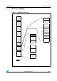
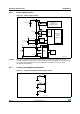
6.1.6 Power supply scheme
Figure 10. Power supply scheme
Caution: Each power supply pair (V
DD
/V
SS
, V
DDA
/V
SSA
etc..) must be decoupled with filtering
ceramic capacitors as shown above. These capacitors must be placed as close as possible
to, or below, the appropriate pins on the underside of the PCB to ensure the good
functionality of the device.
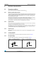
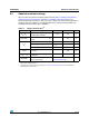
6.1.7 Current consumption measurement
Figure 11. Current consumption measurement scheme
-36
!NALOG
2#S0,,
0O WERSWITCH
6
"!4
'0)/ S
/54
).
+ERNELLOGIC
#05
$IGITAL
-EMORIES
"ACKUPCIRCUITRY
,3%24#
"ACKUPREGISTERS
7AKEUPLOGIC
§N&
§&
6
2EGULATOR
6
$$!
6
33!
!$#
$!#
,EVELSHIFTER
)/
,OGIC
6
$$
N&
&
6
$$!
6
2%&
6
2%&
6
$$
6
33
§
§
-36
6
"!4
6
$$
6
$$!
)
$$
)
$$!
*
%%@7#"5