
Datasheet

Electrical characteristics STM32F051x
50/105 Doc ID 022265 Rev 3
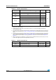
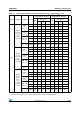
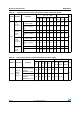
Table 28. Typical and maximum V
DDA
consumption in Stop and Standby modes
Symbol Parameter Conditions
Typ @V
DD
(V
DD
= V
DDA
)Max
(1)
Unit
2.0 V 2.4 V 2.7 V 3.0 V 3.3 V 3.6 V
T
A
=
25 °C
T
A
=
85 °C
T
A
=
105 °C
I
DDA
Supply
current in
Stop mode
V
DDA
monitoring ON
Regulator in run mode,
all oscillators OFF
1.85 2 2.15 2.3 2.45 2.6 3.5 3.5 4.5
µA
Regulator in low-power
mode, all oscillators
OFF
1.85 2 2.15 2.3 2.45 2.6 3.5 3.5 4.5
Supply
current in
Standby
mode
LSI ON and IWDG ON 2.25 2.5 2.65 2.85 3.05 3.3 - - -
LSI OFF and IWDG
OFF
1.75 1.9 2 2.15 2.3 2.5 3.5 3.5 4.5
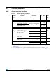
Supply
current in
Stop mode
V
DDA
monitoring OFF
Regulator in run mode,
all oscillators OFF
1.11 1.15 1.18 1.22 1.27 1.35 - - -
Regulator in low-power
mode, all oscillators
OFF
1.11 1.15 1.18 1.22 1.27 1.35 - - -
Supply
current in
Standby
mode
LSI ON and IWDG ON 1.5 1.58 1.65 1.78 1.91 2.04 - - -
LSI OFF and IWDG
OFF
1 1.02 1.05 1.05 1.15 1.22 - - -
1. Data based on characterization results, not tested in production.
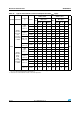
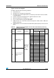
Table 29. Typical and maximum current consumption from V
BAT
supply
Symbol Parameter Conditions
Typ @ V
BAT
Max
(1)
Unit
= 1.65 V
= 1.8 V
= 2.4 V
= 2.7 V
= 3.3 V
= 3.6 V
T
A
=
25 °C
T
A
=
85 °C
T
A
=
105 °C
I
DD
_
VBAT
Backup
domain
supply
current
LSE & RTC ON; "Xtal
mode": lower driving
capability;
LSEDRV[1:0] = '00'
0.41 0.43 0.53 0.58 0.71 0.80 0.85 1.1 1.5
µA
LSE & RTC ON; "Xtal
mode" higher driving
capability;
LSEDRV[1:0] = '11'
0.71 0.75 0.85 0.91 1.06 1.16 1.25 1.55 2
1. Data based on characterization results, not tested in production.