
Datasheet


List of figures STM6510
4/26 Doc ID 16788 Rev 2
List of figures
Figure 1. Logic diagram . . . . . . . . . . . . . . . . . . . . . . . . . . . . . . . . . . . . . . . . . . . . . . . . . . . . . . . . . . . . 6
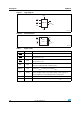
Figure 2. Pin connections . . . . . . . . . . . . . . . . . . . . . . . . . . . . . . . . . . . . . . . . . . . . . . . . . . . . . . . . . . 6
Figure 3. Block diagram . . . . . . . . . . . . . . . . . . . . . . . . . . . . . . . . . . . . . . . . . . . . . . . . . . . . . . . . . . . . 7
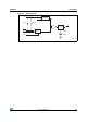
Figure 4. Single-button Smart Reset™ typical hookup . . . . . . . . . . . . . . . . . . . . . . . . . . . . . . . . . . . . 8
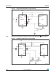
Figure 5. Dual-button Smart Reset™ typical hookup. . . . . . . . . . . . . . . . . . . . . . . . . . . . . . . . . . . . . . 8
Figure 6. Timing waveforms. . . . . . . . . . . . . . . . . . . . . . . . . . . . . . . . . . . . . . . . . . . . . . . . . . . . . . . . . 9
Figure 7. Supply current (I
CC
) vs. temperature . . . . . . . . . . . . . . . . . . . . . . . . . . . . . . . . . . . . . . . . . 11
Figure 8. Smart Reset™ delay (t
SRC
) vs. temperature, C
SRC
= 0.56 µF . . . . . . . . . . . . . . . . . . . . . . 11
Figure 9. Reset timeout period (t
REC
) vs. temperature, C
tREC
= 0.01 µF . . . . . . . . . . . . . . . . . . . . . 12
Figure 10. Reset threshold (V
RST
) vs. temperature, “S” threshold option, V
CC
falling. . . . . . . . . . . . . 12
Figure 11. AC testing input/output waveforms . . . . . . . . . . . . . . . . . . . . . . . . . . . . . . . . . . . . . . . . . . . 14
Figure 12. TDFN – 8-lead 2 x 2 x 0.75 mm, 0.5 mm pitch package outline . . . . . . . . . . . . . . . . . . . . . 18
Figure 13. Landing pattern - TDFN – 8-lead 2 x 2 mm without thermal pad . . . . . . . . . . . . . . . . . . . . 19
Figure 14. Carrier tape . . . . . . . . . . . . . . . . . . . . . . . . . . . . . . . . . . . . . . . . . . . . . . . . . . . . . . . . . . . . 20
Figure 15. Reel dimensions . . . . . . . . . . . . . . . . . . . . . . . . . . . . . . . . . . . . . . . . . . . . . . . . . . . . . . . . . 21
Figure 16. Tape trailer/leader. . . . . . . . . . . . . . . . . . . . . . . . . . . . . . . . . . . . . . . . . . . . . . . . . . . . . . . . 22
Figure 17. Pin 1 orientation . . . . . . . . . . . . . . . . . . . . . . . . . . . . . . . . . . . . . . . . . . . . . . . . . . . . . . . . . 22
Figure 18. Package marking, top view. . . . . . . . . . . . . . . . . . . . . . . . . . . . . . . . . . . . . . . . . . . . . . . . . 24