
Datasheet


Description STM6510
6/26 Doc ID 16788 Rev 2
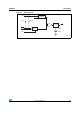
Figure 1. Logic diagram
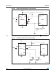
Figure 2. Pin connections
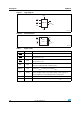
Table 1. Signal names
Symbol Input/output Description
RST
Output Reset output, active-low (open-drain).
SR0 Input
Primary push-button Smart Reset™ input. Active-low, internal 65 kΩ
pull-up resistor to V
CC
.
SR1 Input
Secondary push-button Smart Reset™ input. Active-low, internal 65 kΩ
pull-up resistor to V
CC
.
SRC Input
Smart Reset™ input delay setup control. Connect an external capacitor
to this pin to adjust the delay setup time (t
SRC
).
TREC
ADJ
Input
Input pin for t
REC
reset pulse duration adjustment. Connect an external
capacitor (C
tREC
) to this pin to determine t
REC
.
V
CC
Supply
Supply voltage input. Power supply for the device and an input for the
monitored supply voltage. A 0.1 µF decoupling ceramic capacitor is
recommended to be connected between V
CC
and V
SS
pins.
V
SS
Supply Ground
NC No connect (not bonded); should be connected to V
SS.
AM00389a
V
CC
RST
TREC
ADJ
V
SS
STM6510
SR1
SR0
SRC
AM00390
NC
TREC
ADJ
SRC
1
2
3
STM
6510
4
8
7
6
5
RST
V
SS
V
CC
SR1
SR0