
Datasheet

Electrical characteristics STM8AF52/62xx, STM8AF51/61xx
62/110 Doc ID 14395 Rev 9
Current consumption for on-chip peripherals
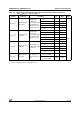
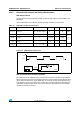
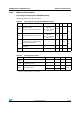
Table 29. Total current consumption in Halt and Active-halt modes. General conditions for V
DD
applied. T
A
= −40 °C to 55 °C unless otherwise stated
Symbol Parameter
Conditions
Typ Max Unit
Main
voltage
regulator
(MVR)
(1)
Flash
mode
(2)
Clock source and
temperature condition
I
DD(H)
Supply current in
Halt mode
Off
Power-
down
Clocks stopped 5 35
(3)
µA
Clocks stopped,
T
A
= 25 °C
525
I
DD(AH)
Supply current in
Active-halt mode
with regulator on
On
Power-
down
External clock 16 MHz
f
MASTER
= 125 kHz
770 900
(3)
LSI clock 128 kHz 150 230
(3)
Supply current in
Active-halt mode
with regulator off
Off
Power-
down
LSI clock 128 kHz 25 42
(3)
LSI clock 128 kHz,
T
A
= 25 °C
25 30
t
WU(AH)
Wakeup time from
Active-halt mode
with regulator on
On
Operating
mode
T
A
=−40 to 150 °C
10 30
(3)
µs
Wakeup time from
Active-halt mode
with regulator off
Off 50 80
(3)
1. Configured by the REGAH bit in the CLK_ICKR register.
2. Configured by the AHALT bit in the FLASH_CR1 register.
3. Data based on characterization results. Not tested in production.
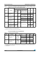
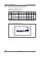
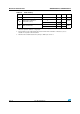
Table 30. Oscillator current consumption
Symbol Parameter Conditions Typ Max
(1)
Unit
I
DD(OSC)
HSE oscillator current
consumption
(2)
Quartz or
ceramic
resonator,
CL = 33 pF
V
DD
= 5 V
f
OSC
= 24 MHz 1 2.0
(3)
mA
f
OSC
= 16 MHz 0.6 —
f
OSC
= 8 MHz 0.57 —
I
DD(OSC)
HSE oscillator current
consumption
(2)
Quartz or
ceramic
resonator,
CL = 33 pF
V
DD
= 3.3 V
f
OSC
= 24 MHz 0.5 1.0
(3)
f
OSC
= 16 MHz 0.25 —
f
OSC
= 8 MHz 0.18 —
1. During startup, the oscillator current consumption may reach 6 mA.
2. The supply current of the oscillator can be further optimized by selecting a high quality resonator with small R
m
value. Refer
to crystal manufacturer for more details
3. Informative data.