
Datasheet

STM8AF52/62xx, STM8AF51/61xx Electrical characteristics
Doc ID 14395 Rev 9 81/110
10.3.10 I
2
C interface characteristics
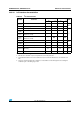
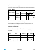
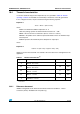
Table 44. I
2
C characteristics
Symbol Parameter
Standard mode I
2
C Fast mode I
2
C
(1)
1. f
MASTER
, must be at least 8 MHz to achieve max fast I
2
C speed (400 kHz)
Unit
Min
(2)
2.
Data based on standard I
2
C protocol requirement, not tested in production
Max
(2)
Min
(2)
Max
(2)
t
w(SCLL)
SCL clock low time 4.7 — 1.3 —
µs
t
w(SCLH)
SCL clock high time 4.0 — 0.6 —
t
su(SDA)
SDA setup time 250 — 100 —
ns
t
h(SDA)
SDA data hold time 0
(3)
3.
The maximum hold time of the start condition has only to be met if the interface does not stretch the low
time
—0
(4)
4.
The device must internally provide a hold time of at least 300 ns for the SDA signal in order to bridge the
undefined region of the falling edge of SCL
900
(3)
t
r(SDA)
t
r(SCL)
SDA and SCL rise time
(V
DD
3 V to 5.5 V)
— 1000 — 300
t
f(SDA)
t
f(SCL)
SDA and SCL fall time
(V
DD
3 V to 5.5 V)
— 300 — 300
t
h(STA)
START condition hold time 4.0 — 0.6 —
µs
t
su(STA)
Repeated START condition setup time 4.7 — 0.6 —
t
su(STO)
STOP condition setup time 4.0 — 0.6 — µs
t
w(STO:STA)
STOP to START condition time
(bus free)
4.7 — 1.3 — µs
C
b
Capacitive load for each bus line — 400 — 400 pF