
Datasheet

DocID5558 Rev 10 3/14
TS431 Electrical characteristics
2 Electrical characteristics
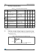
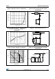
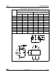
2.1 Definition of output voltage change over temperature range
V
ref
is defined as the difference between the maximum and minimum values obtained over
the full temperature range.
V
ref
= V
ref max
- V
ref min
Figure 1. Output voltage change over temperature range
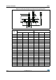
Table 3. T
amb
= 25°C (unless otherwise specified)
Symbol Parameter Test conditions Min. Typ. Max. Unit
V
ref
Output voltage
V
KA
= V
ref
@ I
k
= 100A
TS431
TS431A
TS431B
1.215
1.228
1.234
1.240 1.265
1.252
1.246
V
V
ref
Output voltage change
(1)
(2)
I
k
= 100A, V
KA
= V
ref
0 < T
amb
< +70°C
-40 < T
amb
< +85°C
-40 < T
amb
< +105°C
-40 < T
amb
< +125°C
9
16
18
21
mV
Ratio of change in reference input
voltage to change in cathode to
anode voltage
I
k
= 10mA
V
KA
= 6V to V
ref
1.8 2.7 mV/V
I
ref
Reference input current I
k
= 10mA 70 160 nA
I
ref
Reference input current deviation
over temperature range
I
k
=10mA, R
1
=10k R
2
=
-40 < T
amb
< +85°C
-40 < T
amb
< +125°C
70
90
160
240
nA
I
min
Minimum cathode current for
regulation
V
KA
= V
ref
40 60 A
I
off
Off-state cathode current V
KA
= 6V, V
ref
= 0 0.001 0.1 A
R
KA
Static impedance V
KA
= V
ref
, I
k
= 0.1 to 15mA 0.2 0.4
1. Limits are 100% production tested at 25°C. Behavior at the temperature range limits is guaranteed through correlation and
by design.
2. See definition below.
Vref
Vka
----------------
T1
T2
T
e
m
p
e
r
a
t
u
r
e
Vref min.
Vref max.