
Operating Instructions


5
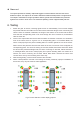
connection.
2. Hook up the 4PIN FEMALE jack to the Monitor and 4PIN MALE plug for camera.
3. The master controller should be hooked by the custom wire harness for VIDEO IN & VIDEO
OUT. The port (Data Link) on the bottom-right of the master controller is connected to the
bottom-left port (Data Link) of the extension controller via the 461-10 cable.
4. The sensor output cables should be plugged in sequences.
5. The controllers and camera are both powered by monitor, which is powered by vehicle battery
through DC Wire or Cigar Lighter.
6. Notice: *Leave the output signal cable from sensors unconnected for testing use.
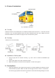
Trigger in
The system provides an auxiliary input that allows an external signal input to change the sensor
status between standby and active. As a backing sensor application, single white wire of extension
cable connects to positive power wire of the back-up light.