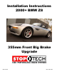
Installation Instructions 2000+ BMW Z8 355mm Front Big Brake Upgrade 98-139-1470 Rev.
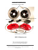
C OMPONENT IDENTIFICA TION IDENTIFICATION 355mm AeroRotor and Hat Assemblies High Performance Street Pads Caliper Brackets ST-40 Calipers Stainless Braided Lines and Hardware BMW Z8 Big Brake Kit This is a representative photograph. The actual components in your kit may appear slightly different. 3541 Unit A, Lomita Boulevard, Torrance, CA 90505 (310) 325-4799 www.stoptech.
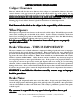
APPLICA TION DISCL AMER APPLICATION DISCLAMER Caliper Clearance Most 18” wheels will clear the outer diameter of the caliper on a 355mm kit. However, the more critical clearance is the gap between the spokes of the wheel and the face of the caliper. Do not assume a 19, 20 or even 24 inch wheel will clear the face of the caliper. The actual metal-to-metal distance measured from the stock rotor face to the inside of the wheel spokes is 58.72 mm for the Z8 F ecommend at least 2mm of additional clear ance.
I mpor tant Notices Wheel Fitment: Do not assume your wheels will fit. An outline drawing of your StopTech Big Brake kit is available on our website at http://www.stoptech.com. Measure the distance from the outer face of your stock caliper to the inner face of your wheel spokes, or make a template according to the instructions on the website and determine if a wheel spacer may be necessary.
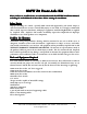
BMW Z8 F it Frr ont Axle K Kit Please, believe us us,, it will be better to read and understand this ENTIRE Installation Manual, including the included B es befor ting the installation. Brreak-in P Prr ocedur ocedures beforee star starting Safety Notice Improper handling of a vehicle, especially while raised and supported by jack stands, ramps or other mechanical means can cause serious bodily injury or even death.
- DOT 3 or 4 Brake Fluid. Check manufactures’ recommendation for compatibility. StopTech recommends flushing brake fluid every 1-2 years, or more often under severe usage conditions. If not done recently, the installation of a brake kit is an excellent opportunity to refresh your brake fluid or upgrade to a higher performance fluid such as Motul 600.
Step 1 (continued) Note: All P hotographs SSho ho w Right SSide ide IInstallation nstallation U nless N oted O ther wise. Photographs how Unless Noted Other therwise. After securing the vehicle at a convenient height, remove the front wheels. Step 2 Disconnect Stock Brake Line WARNING - B r ake fluid will damage most painted sur faces. IImmediately mmediately clean spilled surfaces. br ake fluid fr om any painted sur faces. brake from surfaces.
Step 3 Remove Stock Caliper & Rotor Note: It is helpful to turn the steering away from the side you are working on so the wrench handle clears the rear of the wheel well. The Z8 has a pad wear sensor on the left front and right rear corners. These sensors can be car efully rremo emo om the stock brake pad and rre-inser e-inser ted into the new pad in the SStopT topT ech carefully emovved fr from e-inserted topTech ST -40 caliper e-r oute the lead wir e, which can typically be tyST-40 caliper..
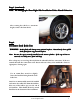
Step 4 Remove Slash Guard/Dust Shield Use a 10mm wrench or socket to remove the four bolts holding the dust shield. Step 5 Install Caliper Bracket The brackets are marked “L” & “R” for Left and Right sides of the vehicle as viewed from the rear of the vehicle looking forward. It may be necessary to slightly clearance the mounting lug on the knuckle. This modification in no way compromises the strength of the part. Bracket shown attached to knuckle using stock caliper mounting bolts.
Step 5 Install Caliper Bracket (continued) File this area If the caliper bracket does not sit flat and the bolts do not line up, it may be necessary to file the outer edge of the mounting lugs as shown above. The image to the right shows the lower lug noting where to file. After proper fit of the bracket has been confirmed, install the caliper bracket as shown on the previous page. Torque caliper bracket bolts to 80-85 lb-ft lb-ft.
Step 6 (continued) Install hat and rotor assembly and hold in place with the stock retaining fastener. Be sure rotor is seated squarely on hub face. If necessary, clean the face of the hub with a wire brush or similar means. B e sur otor assemblies ar ect side of the car suree the rrotor aree on the corr correct car.. Reversing the rotors will severely decrease the cooling capacity of the system.
Left Side Rotor Outboard Side D riv er river er’’s Left Right Side Rotor Outboard Side D riv er river er’’s Right 3541 Unit A, Lomita Boulevard, Torrance, CA 90505 (310) 325-4799 www.stoptech.
3541 Unit A, Lomita Boulevard, Torrance, CA 90505 (310) 325-4799 www.stoptech.
Caliper Component Identification Bolt-in Bridge Pad Retaining Clip Cross Over Tube Bleed Screw Bridge Bolts Use a light film of Anti-Sieze on Bridge Bolt shaft and threads The ST-40 caliper uses a Porsche style pad. The Friction Materials Standards Institute (FMSI) number for the pad backing plate is D372 Please see the FAQ section of our website for further pad interchange information. www.stoptech.
Step 7 Install Caliper and Pads - Determine the left and right side calipers. The calipers are marked on each box. As a check, the bleed screws always go to the top of the caliper. Remove the 2 bolts holding the caliper bridge using a 5mm Allen wrench. Remove the caliper bridge taking note of the direction it is installed in and the correct location of the pad retaining wire clip, which typically, but not always, stays attached to the bridge.
Step 7 (Continued) Note- Images on this and the following page may not be of the vehicle noted however they are a proper represention of the correct installation. Install the caliper onto the adapter bracket studs with the bleed screws on the top side of the caliper. Slide the caliper over the mounting studs, making sure it is square and evenly started on both studs. It may necessary to gently tap the caliper into position with a non-marring hammer or mallet.
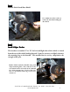
Step 7 (continued) Install the bridge by sliding it into position and rocking it until one of the bolt holes lines up. Be sure the bridge is slid straight and parallel into the caliper body opening. Note: The bridge is directional and the “air-scoop ” detail should face do wn on the air-scoop” down Supra kit. Apply a light film of anti-sieze compound onto the bridge bolt shaft and threads. Insert the first bridge bolt and start the first few threads using a 5mm Allen wrench.
Step 8 Attach the stainless brake line Install the banjo bolt into the caliper with a copper crush washer on each side of the Banjo fitting. Route the line vertically, approximately parallel with the caliper body. Copper Crush Washers Banjo Bolt o ximately 14 lb-ft using a 14mm wrench. Torque to appr appro The Banjo bolt only needs to be tightened enough to seal the crush washers. Excessive torque can damage the threads inside the caliper and/or damage the Banjo bolt.
Step 9 Bleed Brakes Complete installation on both sides of the vehicle before bleeding the system. Note: The calipers and lines will need to fill with fluid, quickly draining the master cylinder reservoir. Keep a close watch on the fluid level when initially bleeding the system. Do not allow the master cylinder reservoir to run dry and draw in air. Doing so may require the brake system to be serviced by a certified brake technician.
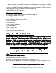
Step 10 Re-install wheels Check wheel to caliper clearance before installing wheels! Note: Some wheels are balanced on the inside with adhesive backed lead. If the lead is on the outboar d edge, behind the spokes, it may inter fer outboard interfer feree with the caliper caliper..
AeroRotorTM Installation & Break-in Procedure READ THIS NOW FAIL URE TO READ, UNDERST AND AND FOLL OW THESE PR OCEDURES AILURE UNDERSTAND FOLLO PROCEDURES WILL CAUSE PERMANANT DAMAGE TO YOUR BRAKE ROTORS AND KEEP THE SYSTEM FR OM WORKING A T IT ’S FULL CAP ACIT Y. FROM AT IT’S CAPA CITY The majority of brake system problems are due to improper installation and/or break-in of the rotors and pads.
Rotor and Pad Break-in (continued) NoteBedding of pads should not be done in wet weather or wet road conditions. After completeing installation, make a series of 10 stops from 60 to 5-10 MPH. At the end of each stop, immediately accelerate to 60 again for the next stop. Run all stops in one cycle. During the 60 to 5-10 MPH series of stops, the exact speed is not critical. Accelerate to appoximately 60 and begin the braking cycle.
Thank you for selecting StopTech, we realize you had a choice in selecting a big brake upgrade for your vehicle and know youll be happy with our system. We proudly support our fine products. For any assistance or questions, please contact our Customer Service Departmant at (310) 325-4799 extension 105 or e-mail us at support@stoptech.com.