Installation Instructions 2000+ BMW E39 M5 and 5-Series 355mm Rear Big Brake Upgrade ST-40 Caliper 98-135-1471 Rev.
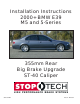
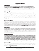
COMPONENT IDENTIFICA TION IDENTIFICATION AeroRotor and Hat Assemblies High-Performance Street Pads Caliper Brackets Calipers Stainless Steel Braided Lines and Hardware BMW E39 M5 and 5-Series Rear Big Brake Kit This is a representative photograph. The actual components in your kit may appear slightly different. 3541 Unit A, Lomita Boulevard, Torrance, CA 90505 (310) 325-4799 www.stoptech.
APPLICA TION DISCL AIMER APPLICATION DISCLAIMER Per manent R emo ust SShield hield ermanent Remo emovval of D Dust The dust shield must be permanently removed from both rear wheels of the vehicle, to accommodate the AeroRotors. This involves cutting each shield with sheet metal snips or a power cut-off wheel, and de-burring sharp edges with a file or power die grinder. These operations can be dangerous, and serious injury can occur.
APPLICA TION DISCL AIMER (Cont APPLICATION DISCLAIMER (Cont’’d.) Wheel SSpacers pacers Wheel spacers can provide extra clearance to the outer face of the caliper. This will also space out the entire wheel, widening the track width of the vehicle. Fender clearances should be checked on lowered cars, and longer lug studs or wheel bolts are usually required. Note: The Wheel IIndustr ndustr ouncil has issued guidelines advising that wheel spacers not be ndustryy C Council used.
Impor tant N otices mportant Notices Wheel F itment Fitment Do not assume that your wheels will fit. An outline drawing of your StopTech Big Brake kit is .stoptech.com available on our website at www www.stoptech.com .stoptech.com. Measure the distance from the outer face of your stock caliper to the inner face of your wheel spokes, or make a template according to the instructions on the website, to determine if a wheel spacer is necessary.
BMW E39 M5 and 5-Series Rear Axle Kit Note: IItt is impor tant to rread ead and understand this ENTIRE installation manual, including the important break-in procedures, before starting the installation. Kit Contents Your StopTech Big Brake kit includes the following: 1 pair of ST-40 four-piston calipers, sized specifically for your vehicle 1 set of high-performance street pads (not suitable for track use) 1 pair of 355 X 32mm two-piece rotor assemblies 1 pair of aluminum caliper adapter brackets 4 ea.
Step 1 R aise Vehicle, and R emo Remo emovve Wheels N ote: A ll photogr aphs sho w a right-hand side installation, unless other wise noted. All photographs show otherwise A level, stable and clean surface, suitable for supporting the vehicle on jack-stands, should be used for the installation. War ning: N ev er leav ehicle suppor ted arning: Nev ever leavee any vvehicle supported with only a jack. Always use jack-stands. Break loose the lug nuts on both rear wheels before jacking up the car.
Step 2 Disconnect SStock tock B rake Line Brake War ning: B faces. IImmediately mmediately clean spilled br ake arning: Brrake fluid will damage most painted sur surfaces. brake fluid from any painted surface. Also be sure that the cap is securely installed on the master cylinder emo ake cylinder.. If the cap is loose or rremo emovved, it is likely that mor moree fluid will drip during br brake installation. Place a drip tray or several rags directly below the inboard brake line connection.
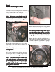
Step 3 Remo tock C aliper & R otor emovve SStock Caliper Rotor Carefully remove the stock pad-wear sensor from the caliper, and place it out of the way temporarily, so that it will not be damaged. Note: T ake car Take caree to ensur ensuree that the metal clip which is located around the outside of the padwear sensor does not come loose and get lost. Remove the two stock caliper bolts, using a 16mm socket, which is fitted with an extension.
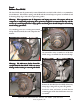
Step 4 Remo ust SShield hield emovve D Dust The dust shield must be permanently removed from both rear wheels of the vehicle, to accommodate the AeroRotors. This involves cutting each shield with sheet metal snips or a power cut-off wheel, and de-burring sharp edges with a file or power die grinder. ations can be danger ous, and injur or any one who is not War ning: These oper arning: operations dangerous, injuryy can occur occur..
Step 5 Install Caliper Bracket Remove the jet nuts and washers from the caliper bracket, and put them in a safe place for later use. Install the caliper bracket, using a 16mm wrench or socket to tighten the stock caliper mounting bolts. Torque the bolts to 50-55 lb-ft lb-ft. 3541 Unit A, Lomita Boulevard, Torrance, CA 90505 (310) 325-4799 www.stoptech.
Step 6 Install AeroRotor Assembly AeroRotors MUST be cleaned with soap and water prior to installation (soap and warm water work best to remove all traces of rust inhibitor, but brake cleaner can be used as an alternative, if necessary). Not cleaning the AeroRotors will damage the rotors and pads, and will prevent the brakes from performing properly. Even though the rotors may look clean, the rust inhibitor is in place, and it must be removed.
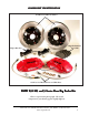
Left-Side Rotor Outboard Side Driv er river er’’s Left Right-Side Rotor Outboard Side Driv er river er’’s Right 3541 Unit A, Lomita Boulevard, Torrance, CA 90505 (310) 325-4799 www.stoptech.
3541 Unit A, Lomita Boulevard, Torrance, CA 90505 (310) 325-4799 www.stoptech.
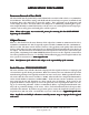
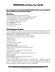
Caliper Component IIdentification dentification Bolt-in Bridge Pad-retaining Clip Cross Over Tube Bridge Bolts Bleed Screw Use a light film of anti-seize compound on the bridge bolt shafts and threads The ST-40 original equipment caliper uses a pad that is common to two-piston opposed calipers. The Friction Materials Standards Institute (FMSI) number for the pad backing plate is D372. For further pad interchange information, please see the FAQ section of the StopTech website at: www.stoptech.
Step 7 Install C aliper and P ads Caliper Pads Note: The images in this section may not be of the vehicle noted, but they give a proper representation of the correct installation. Determine the left- and right-hand side calipers. They are clearly marked on the box, but as a check, the bleed screws are always positioned at the top of the caliper. If installing a four-wheel kit, with ST40 calipers on the front and rear of the vehicle, be sure that the correct caliper is on each corner.
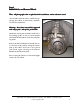
Step 7 (Cont (Cont’’d.) Install C aliper and P ads Caliper Pads Install the stainless steel brake line onto the caliper, using a 14mm wrench to tighten the line fitting. Install the caliper onto the adapter bracket, orienting it so that the bleed screws are on the top side of the caliper. Take care to ensure that the caliper is square and evenly started on both studs. It may be necessary to use a mallet to gently tap the caliper into position.
Step 7 (Cont (Cont’’d.) Install C aliper and P ads Caliper Pads Install the bridge by sliding it into position, and rocking it until one of the bolt holes lines up. Take care to ensure that the bridge is slid straight and parallel into the caliper body opening. Note: The bridge is dir ectional, and should directional, be positioned so that the air-scoop opening is located in the bottom half of the caliper caliper..
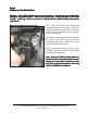
Step 8 Attach SStainless tainless SSteel teel B rake Line Brake Reinsert the rubber washers on either side of the inboard brake line bracket, then remove the rubber cap from the hard line, and screw the stainless steel brake line onto the hard line fitting by hand for a few turns. Use a 14mm wrench to hold the stainless line inboard fitting, while using an 11mm flare wrench to tighten the hard line fitting.
Step 9 Bleed Brakes Complete the installation on both sides of the vehicle before bleeding the system. War ning: D ouble-check that the stainless steel br ake lines yyou ou arning: Double-check brake ou’’v e just installed ar aree not binding in any way, nor interfering with any suspension component, including the CV boot and the axle/ drive shaft. Adjust each line, if necessary, by loosening the inboard end of the line, and slightly re-clocking the fitting.
Step 10 Reinstall Wheels It is very important to check the wheel-to-caliper clearance before installing wheels! Note: S ome wheels ar e-backed lead w eights. If the Some aree balanced on the inside, with adhesiv adhesive-backed weights. d edge, behind the spokes, it may inter fer weight is on the outboar outboard interfer feree with the caliper caliper..
AeroRotorTM Installation & Bed-in Procedure READ THIS NOW FAIL URE TO READ, UNDERST AND AND FOLL OW THESE PR OCEDURES AILURE UNDERSTAND FOLLO PROCEDURES WILL CA USE P ERMANENT DAMA GE TO YOUR BRAKE R OTORS, AND WILL CAUSE PERMANENT DAMAGE RO KEEP THE SYSTEM FR OM WORKING A T IT S FULL CAP ACIT Y. CITY FROM AT ITS CAPA The majority of brake system problems are due to improper installation and/or bed-in of the rotors and pads.
Rotor and P ad Bed-in (Cont Pad (Cont’’d.) Note: B edding-in of pads should not be done in poor w eather conditions, nor on w et rroads. oads. Bedding-in weather wet After completing the installation, make a series of 10 stops from 60 to 5-10 MPH. At the end of each stop, immediately accelerate to 60 again for the next stop. Run all stops in one cycle. During the 60 to 5-10 MPH cycle of stops, the exact speed is not critical. Accelerate to approximately 60, then begin braking.
Thank yyou ou for selecting SStopT topT ech. topTech. We realize that you had a choice when selecting a big brake upgrade for your vehicle, and we know that you’ll be happy with our system. We proudly support our fine products. For any assistance or questions, please contact our Customer Service Department at (310) 325-4799 - extension 105 or e-mail us at support@stoptech.