CAUTION RISK OF ELECTRIC SHOCK DO NOT OPEN TO REDUCE THE RISK OF ELECTRIC SHOCK, DO NOT REMOVE THE COVER. NO USER SERVICABLE PARTS INSIDE. REFER SERVICING TO QUALIFIED PERSONNEL. The lightning flash with arrowhead symbol, within an equilateral triangle, is intended to alert the user to the presence of noninsulated “dangerous voltage” within the product’s enclosure that may be of sufficient magnitude to constitute a risk of electric shock.
IMPORTANT SAFEGUARD All lead-free products offered by the company comply with the requirements of the European law of the Restriction of Hazardous Substances (RoHS) directive, which means our manufacturing processes and products are strictly “lead-free” and without the hazardous substances cited in the directive. The crossed-out wheeled bin mark symbolizes that within the European Union the product must be collected separately at the product’s end-of-life.
TABLE OF CONTENTS QUICK START GUIDE 1.1 – Basic Connectivity 1.2 – Wall Mounting A Camera 1.3 – Power Connection Diagram OVERVIEW 6 6 7 8 9 2.1 – System Overview 2.2 – Environment Adaptability 2.3 – Recording Capacities 9 9 9 CONVENTIONS USED IN THIS MANUAL 10 PACKAGE CONTENTS 10 SYSTEM CONNECTION 11 5.1 – Connectivity Diagram BASIC OPERATION 6.1 – Front Panel 6.2 – Rear Panel 6.3 – Remote Control 6.4 – Mouse Control 6.5 – Using The Sub Menu 6.6 – Power On / Off 6.7 – Pass Codes 6.
TABLE OF CONTENTS (CONTINUED) ADVANCED MENU FUNCTIONS 32 8.1 – Advanced Setup 8.2 – Alarm 8.3 – E-Mail Setup 8.4 – System Info 8.5 – Motion Detection 8.6 – Mobile 8.7 – System 8.8 – Firmware Upgrade 8.9 – Parameter Export 8.10 – Parameter Import 8.11 – Pan Tilt Zoom (PTZ) 8.12 – Network 8.13 – DDNS 8.14 – UPnP 32 33 34 35 35 36 37 38 38 38 39 40 41 42 REMOTE SURVEILLANCE SOFTWARE 43 9.1 – Using Remote Surveillance 9.2 – Main Screen 9.3 – Live View 9.4 – Recording 9.5 – Sub Menu 9.6 – PTZ Control 9.
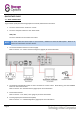
QUICK START GUIDE 1.1 – BASIC CONNECTIVITY To get started quickly with the Storage Options CCTV DVR, follow these instructions: 1. Connect a camera to the “Video In 1” socket. 2. Connect a computer monitor to the “VGA” socket. AND / OR Connect a television to the “Video Out” socket. NOTE You must select the correct input on your monitor / television to view the DVR system. Refer to its manual for instructions on how to do this. 3. Connect the DVR and camera to a mains supply. Refer to section “1.
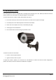
1.2 – WALL MOUNTING A CAMERA Each Storage Options camera is supplied with a mounting kit for attaching it to a wall. Before you affix the camera in position, please ensure the cable is of adequate length to reach the DVR. To mount the camera on a wall or ceiling, follow these instructions: 1. Ensure the surface you want to mount the camera on is solid and can support the weight. 2. Accurately mark on the wall the position of the holes to be drilled. 3.
1.3 – POWER CONNECTION DIAGRAM This system is supplied a 1-5 power splitter cable, which allows you to connect the DVR and up to four cameras to a single mains socket. Connect power to the DVR and cameras as shown in this diagram: BLUE = Camera mains connection RED = DVR mains connection YELLOW = Video connection The 1-5 power splitter cable has one red and four black plugs. Connect the red cable to the DVR. Connect one of the black cables to the included camera.
OVERVIEW 2.1 – SYSTEM OVERVIEW Installing this DIY Home CCTV Kit could be one of the best steps you ever take to secure your home or business premises. As well as protecting against criminal activity and actively deterring criminals from targeting your property and vehicles, it will bring additional peace of mind for you and your family.
CONVENTIONS USED IN THIS MANUAL At various points in this manual you will see highlighted text. Please refer here for an explanation: NOTE TIP Important notes are highlighted in blue. Tips on best practice are highlighted in green. CAUTION Important cautions and warnings are highlighted in red. Unless otherwise stated, all functionality described in this manual is performed using the USB mouse. PACKAGE CONTENTS Check the contents of your DVR against this checklist.
SYSTEM CONNECTION 5.1 – CONNECTIVITY DIAGRAM Refer to this diagram for the recommended method of connecting this CCTV system. Refer to section “1.3 – Power Connection Diagram” (page 8) for more information on connecting to a mains socket.
BASIC OPERATION 6.1 – FRONT PANEL 1. IR SENSOR: Receives infra-red signals from the remote control. Do not cover. 2. LED INDICATORS: Shows system status. Page 12 LABEL COLOUR DESCRIPTION HDD GREEN Flashes to indicate HDD activity. REC GREEN Indicates whether the DVR is currently recording. NET GREEN Flashes to indicate network traffic. ALM RED Indicates whether an alarm trigger has occurred. POWER RED Indicates whether the DVR is currently powered on.
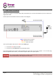
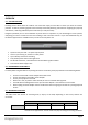
6.2 – REAR PANEL Refer to the diagram and table below for information on the DVR’s various connections.
6.3 – REMOTE CONTROL The remote control can be used for navigating system menus. When using the remote control, the OK key performs the same functions as left-clicking the mouse. To use the remote control with the DVR system: 1. Insert 2x AAA 1.5V alkaline batteries (not included) into the back of the remote control. Please ensure correct orientation. 2.
6.4 – MOUSE CONTROL The mouse can be used for navigating system menus. NOTE Unless otherwise stated, all system functions described in this manual are achieved through mouse input. To use a mouse with the DVR system: Connect the mouse to the lower USB port located on the rear panel (labelled with a mouse icon). Left Button: Click to select a menu option. During live viewing, double-click on a channel to view it in full-screen. Double-click the channel again to return to split-screen grid view.
6.6 – POWER ON / OFF To power the system on, connect the power cable to the DC 12V port on the rear panel. At start-up, the DVR performs a basic system check and runs an initial loading sequence. After a few moments, it will load a live display view. The system can also be put into standby mode. It will still receive power but will not record anything until brought back into operation mode. 1.
6.10 – PLAYBACK The Search Menu can be used to view previously recorded footage. To begin playback: 1. Right-click anywhere on screen and select VIDEO SEARCH from the sub menu. NOTE When the Search Menu is first opened, it displays the current month and date. 2. Click PLAY to begin playback of the last minute of recorded video (quick search). OR Under CHN select a specific channel or select ALL. 3. Under DATE, enter a date using the virtual keyboard (mouse only). 4. Click SEARCH.
BASIC MENU FUNCTIONS 7.1 – MAIN MENU The main menu displays options for controlling every feature of the DVR. See below for an explanation of each of the options on the main menu. RECORD SEARCH: Search for previously recorded video on the system. RECORD: Configure recording options, set record modes, and enable / disable audio recording. HDD: Display HDD status and format the internal hard drive.
7.2 – SEARCH Use this function to search for and play back previously recorded video on the DVR system. When the Search menu is opened for the first time, it will display the current date and time. To perform a quick search, simply open the SEARCH menu and click PLAY. The last 60 seconds of recorded playback will begin. To perform a date and time search: 1. Under CHN, select individual channels or select ALL. 2. Under DATE, enter a desired date using the virtual keyboard, then click SEARCH.
7.3 – FILE LIST Use the File List sub menu to see a detailed list of all the recorded video on your system. To open the file list: 1. From the Search menu, click SEARCH to find recorded video. 2. Select FILE LIST at the bottom of the menu. The File List menu will open. 3. Highlight the required file and select it to begin playback. To use the File List: 1. Under TYPE, select NORMAL to view only normal recordings, ALARM to view triggered recordings (alarm and motion detection), or ALL to view all videos. 2.
7.4 – BACKUP Use the File List sub menu to find recorded video on your system and copy it to a USB flash drive (not included). NOTE The system is compatible with most major brands of USB flash drives, with capacities from 256MB to 4GB. To back up recorded data: 1. Connect a blank USB flash drive to the top USB port on the rear panel of the system. 2. Open the Search menu and search for recorded data on the system. 3. Click FILE LIST. 4. Click the "BAK" box next to a file name to mark it for backup.
7.5 – RECORD MODE Use this page to configure recording parameters and enable / disable audio. NOTE Audio capable cameras (not included) are required for audio recording. To configure recording options: 1. Under CHANNEL, use the drop-down menus and select ON / OFF to enable / disable recording from the selected channel. 2. Under resolution, select CIF, HD1 or D1.
7.5 – RECORD MODE (CONTINUED) 1. Under FRAMERATE, it is possible to adjust in one frame per second increments. 2. Under AUDIO, select ON or OFF. If audio recording is enabled, the system will record audio from any connected audio-capable cameras (not included). 3. Under REC MODE, select POWER UP or TIMER RECORD. POWER UP: TIMER RECORD: The system will start continuous recording as soon as it is powered on. The system will record according to the customisable recording schedule. 4.
7.6 – RECORDING SCHEDULE By default, the system is configured to record continuously, but it is possible to set it to record by customisable recording schedule instead. The Schedule Grid shows the days of the week and hours 0-23. You can set alarm recording (red), general recording (green) or no recording (blue) to each time block of each day. To set a recording schedule: 1. Open the Main Menu and click RECORD. 2. Under REC MODE, select TIMER RECORD. 3. Click SCHEDULE. The Schedule menu will open. 4.
7.7 – HDD MANAGEMENT This page displays essential information about the system’s internal hard drive, and lets you format the HDD or a USB flash drive (not included). HDD STATUS: The system will display “OK” if the HDD is operating correctly, or “No Disk” if a HDD is not present. SIZE: Size (in Gigabytes, GB) of the internal HDD. FREE SPACE: The space (in Gigabytes, GB) remaining on the system’s internal HDD. AVAILABLE TIME: Recording time remaining on the HDD based on current recording settings (e.
7.8 – BASIC SETUP Use this page to set the system language, date and time, pass codes, and configure audio / video and display options. The Basic Setup menu contains the following sub menus: Language Date / Time Password Display Video / Audio Exit 7.9 – LANGUAGE To change the system language: 1. From the drop-down menu select ENGLISH or CHINESE 2. Click APPLY, then click CLOSE in the confirmation window. NOTE Page 26 The DVR will restart when you finish system language setup.
7.10 – DATE / TIME It is highly recommended to set the date and time immediately when first setting up the system. To set the date and time: 1. Click DATE / TIME and configure the following options: DATE: Enter the day, month, and year DATE FORMAT: Select DD/MM/YYYY, MM/DD/YYYY, or YYYY/MM/DD TIME: Enter the time TIME FORMAT: Use the drop-down menu and select 12HOURS or 24HOURS DST: Use the drop-down menu to select ON/OFF to enable/disable Daylight Savings Time 2.
7.12 – PASSWORD The password page allows configuration of up to 6 accounts (1 admin, 5 normal users). The DEVICE ID is a unique numerical identifier (in the case that multiple DVRs are being used in one location). For each user, the following settings are available: 1. USER NAME: Enter the user’s name in this field. 2. LEVEL: Choose either ADMIN or NORMAL. ADMIN: The administrator has access to all system settings. NORMAL: Normal users have limited access to features. 3.
7.13 – USER PERMISSIONS Click PERMISSION on the User Password Setup screen to open the User Permission menu. Here it is possible to choose what the selected user has access to. NOTE This page can only be adjusted by an admin account. Users can see but not change their permissions. NEXT: Continue to the next page of permissions. ALL: Select all permissions. CLEAN: Unselect all permissions. APPLY: Save the current permissions settings. EXIT: Return to the previous menu.
7.14 – DISPLAY Use the display setup menu to customise channel names, show / hide the date and time in live view and playback modes, and enable / disable preview channels. NAME: Enter a new title for the selected channel using the virtual keyboard. POSITION: Reposition the channel title. COLOR: Click SETUP to adjust chromaticity, luminosity, contrast and saturation for the selected channel. LIVE: Choose whether the channel can be seen if the monitor is in public view. See section “7.
7.15 – LIVE Preview channels can be very useful if your display monitor is in public view. 1. Choose a channel you wish to conceal. Under LIVE, select OFF. 2. Click APPLY to save changes. The selected channel will turn black (but what the camera sees will still record). 3. Click CLOSE in the confirmation window, then click EXIT in remaining menus until they are all closed. 7.16 – VIDEO / AUDIO This page allows changes to the VGA output resolution and video system used by the DVR.
ADVANCED MENU FUNCTIONS 8.1 – ADVANCED SETUP Use the Advanced Setup menu to configure alarm settings, motion detection, mobile surveillance, PTZ settings and network settings.
8.2 – ALARM The Alarm menu can be used to configure alarm and e-mail settings. NOTE External alarm devices must be connected to the alarm block on the rear panel of the DVR in order to use the I/O alarms of the system. To configure alarm settings: 1. Under ALARM MANAGE POST REC, select the amount of time the DVR should record for after an alarm event has occurred. 2. For EMAIL SETUP, refer to section “8.3 – E-Mail Setup” (page 34). 3. Click APPLY to save changes, then EXIT to close the menu.
8.3 – E-MAIL SETUP The DVR can send an e-mail notification with a JPEG (single frame) snapshot for triggered events. To set up e-mail notification: 1. Under EMAIL, select ON. 2. Under SSL, select OFF. NOTE SSL deals with encryption. Only advanced users should enable this option. 3. Under SMTP PORT, enter the SMTP port of your e-mail server. 4. Under SMTP, enter the SMTP address of your e-mail server (e.g. smtp.mail.com). 5. Under SEND EMAIL, enter your e-mail address (e.g. user@mail.com). 6.
8.4 – SYSTEM INFO This page shows system information, including the firmware version, MAC address, and system serial number. There are no user-configurable settings on this page. 8.5 – MOTION DETECTION Each channel can be configured to record based on motion being detected in the frame. To configure motion detection: 1. Under STATUS, select ON to enable motion detection for that channel. 2. Under SENSITIVITY, select 1 (low), 2 (medium), 3 (high), or 4 (very high). 3. Under MD AREA, click SETUP.
8.6 – MOBILE It is possible to view footage from the DVR on your smart phone. TIP When using the mobile viewer application “MEye”, please ensure that the “Mobile Port” setting matches the port number on this page. To configure notification settings: 1. Under MOBILE NETWORK, select 3G, 2.75G or 2.5G. 2. Under MOBILE PORT, enter an appropriate mobile port number (we recommend the default “100”). 3. Click APPLY to save changes, then click CLOSE in the confirmation window. 4. Click EXIT to close the menu.
8.7 – SYSTEM Use the System menu to update system firmware and set an automatic system reset schedule. To enable auto-reset: 1. Under AUTO RESET, select ON. The Settings option will appear. 2. Under SETTINGS, select EVERY DAY, EVERY WEEK or EVERY MONTH. The Date drop-down menu will appear. 3. Select the date for auto-reset from the drop-down menu. 4. Enter the time for auto-reset using the virtual keyboard (mouse only). 5. Click APPLY to save changes, then click CLOSE in the confirmation window.
8.8 – FIRMWARE UPGRADE Occasionally a new firmware update may be issued for this DVR. Please check the Storage Options website for more information. To upgrade firmware: 1. Copy the firmware file to an empty USB flash drive. The firmware file should be stored in the root of the drive. 2. Connect the USB flash drive to the top USB port on the front panel of the DVR (labelled “USB 2.0”). 3. Open the System Menu (Main Menu Advance System). 4. Click FIRMWARE UPDATE.
8.11 – PAN TILT ZOOM (PTZ) Use the PTZ Setup menu to configure settings for a connected PTZ camera (not included). NOTE Consult the instruction manual of your PTZ camera for information about your camera, including protocol and baud rate. To configure a PTZ camera: 1. Connect a PTZ camera to the BNC and 485A (TX, +) and 485B (RX, -) ports and power outlet. 2. Under PROTOCOL, select PELCO-D or PELCO-P for the selected channel. 3. Under BAUD RATE, select 1200, 2400, 4800, or 9600. 4.
8.12 – NETWORK Use the Network Setup menu to configure network and DNS settings. NOTE Your router must support UPnP functionality. To configure network settings: 1. Under TYPE, select DHCP, PPPoE or STATIC (if unsure, choose DHCP as this is the most common). TIP For PPPoE, go to step 2 For STATIC, go to step 3 For DHCP, go to step 5 DHCP allows you to quickly connect to your network by automatically obtaining an IP address from the router.
8.13 – DDNS A DDNS account allows you to set up a web site address that points back to your local network. A Web site address is easier to remember than a WAN IP. NOTE You must register an account with a DDNS service provider prior to configuring DDNS settings on the DVR. Visit http://www.dyndns.com to register a free account. To configure DDNS settings: 1. From the Network Setup menu, enter Primary or Secondary DNS from the WAN settings of your router in the MANUAL DNS field. 2. Click DDNS SETTINGS. 3.
8.14 – UPNP The UPnP Forum is an industry initiative designed to enable simple and robust connectivity among consumer electronics, intelligent appliances and mobile devices from many different vendors. As a group, they are dedicated to making the “connected home and lifestyle” mainstream experiences for consumers. To configure UPnP settings: 1. Enable UPnP in your router (refer to your router’s instruction manual for information on how to do this). 2. On the DVR, open the Main Menu and click ADVANCE. 3.
REMOTE SURVEILLANCE SOFTWARE The DVR features built-in browser based software which allows access to the system locally over the Local Area Network (LAN) or remotely over the Internet, using Internet Explorer. Open Internet Explorer and type the DVR’s IP address into the address bar, then press Enter to load the page. On first use, you will be prompted to install ActiveX controls. Please follow on-screen instructions and if you are given the option to block or allow any controls, please allow them.
9.1 – USING REMOTE SURVEILLANCE With your DVR connected to your Local Area Network (LAN), you can log in to the system using Internet Explorer browser. NOTE The DVR must be connected to your local or wide area network before attempting remote access. To Log Into The System: 1. Open Internet Explorer. In the address bar, enter the IP address of the DVR (e.g. http://192.168.0.10). 2. You must install the ActiveX control in order to access the DVR.
9.2 – MAIN SCREEN Once logged in, the Remote Surveillance main screen appears in the browser. REFERENCE ITEM 1 Modes 2 Main Screen Main display screen for live viewing and playback. 3 Time Stamp Time and date for each channel. 4 Channel 5 PTZ Control 6 Functions Click icons to show / hide channels, take screen captures and record. 7 Display Modes Click icons to view channels in full-screen, quad grid and split-screen configurations.
9.3 – LIVE VIEW By default, the browser-based remote surveillance system opens in Live View mode (split-screen). To use Live View: 1. Click LIVE at the top of the main screen. 2. Click the display mode icons to view the main screen in single-channel, quad or split-screen configurations. You can also double-click a channel at any time to view it in single-channel mode. 3. Click to show or hide all the channel windows. 4. Click to start / stop manual recording to your computer on ALL channels.
9.6 – PTZ CONTROL You must have a PTZ camera (not included) connected to the system in order to use the PTZ controls. To control a PTZ camera: 1. Select the channel of the connected PTZ camera. 2. Click the ← or → navigation arrows to pan, and ↑ or ↓ keys to tilt the camera. 3. Click + / - to adjust zoom, focus, and aperture values. 4. Enter presets. 5. Click SETTING, HAND and CLEAR to further control presets. 9.
9.8 – PLAYBACK Use the Replay menu to search and play back recorded video on the system. To use the replay menu: 1. Click REPLAY at the top of the main screen. The main screen will be grey. 2. Click REFRESH below the calendar to view the recorded files for the current month. NOTE Normal recording is indicated by a clock icon; alarm recording (alarm, loss, and motion events) are indicated by an exclamation mark icon. 3. Double-click a file from the File List to play back the file in the main screen.
9.9 – SEARCH Use the calendar and drop-down menus to search for recorded video on your system. 1. Click < or > to change the month on the calendar. Dates with recorded video data will appear in bold. 2. Click the date. Recorded video files will populate the File List. 3. From the Channel drop-down menu, select a specific channel or select ALL CHANNEL and then click SEARCH. 4. From the Type drop-down menu, select COMMON (normal recording), ALARM, or ALL TYPE and then click SEARCH. 5.
9.11 – REMOTE SETUP Use the Setup tab to configure the settings of your system from a remote location. NOTE If the Main Menu is open on the DVR system, you will not be able to make changes to settings from a Web browser. To open remote setup: Click SETUP at the top of the main screen. The Remote Setup menu features the following tabbed options: RECORD ALARM PTZ NETWORK SETTING MAINTENANCE HOST INFO 9.
9.13 – ALARM SETTING Click ALARM to access the setup interface and check or change settings in a similar manner to using the DVR’s GUI. 9.14 – PTZ Click PTZ to access the setup interface and check or change settings in a similar manner to using the DVR’s GUI.
9.15 – NETWORK Click NETWORK to access the setup interface and check or change settings in a similar manner to using the DVR’s GUI. 9.16 – SETTING Click SETTING to access the setup interface and check or change settings in a similar manner to using the DVR’s GUI.
9.17 – MAINTENANCE Click MAINTENANCE to access the system configuration interface. Here you can remotely reboot the DVR, format it’s HDD, or upgrade the system’s firmware. 9.18 – HOST INFO Click HOST INFO to access the system information interface. The interface includes information on the HDD status, remaining record time, firmware version and network MAC address. This page is for information only; there are no user-configurable settings here.
SOFTWARE CD A CD featuring bonus software, manuals and apps has been included with the system. Place the disc in a CD / DVD or Blu-ray drive on your Windows computer and open “My Computer”. Here you can browse the disc contents: Mobile Phone Apps Android Meye.apk MEye_android Blackberry MEye MEye.alx iPhone iPhone_User_Manual Symbian MEye_3rd.sisx MEye_5th.sisx Windows Mobile Meyesetup Instructions for Mobile Phone Monitor Windows PC Playback Software Playback Setup v.2.3.4.
REMOTE ACCESS To access this product from a remote location (i.e. outside your current network), your Internet router will need to have port forwarding rules in place. This will allow traffic from the Internet to pass through the router’s firewall and to your Storage Options system.
HARD DISK DRIVE INSTALLATION If you are at all hesitant to perform the following procedure, please refer to qualified service personnel. Follow these steps to install a HDD: CAUTION When working with electrostatic sensitive devices such as a Hard Disk Drive (HDD) or DVR unit, make sure you use a static-free workstation. Any electrostatic energy coming in contact with the hard disk or DVR can damage it permanently. 1.
TROUBLESHOOTING If a solution to your problem is not listed below, please call our technical support team (see below). PROBLEM System is not receiving power, or is not powering up. POSSIBLE CAUSES SOLUTIONS Cable from power adapter is loose or unplugged. Cables are connected but system is not receiving sufficient power. Remote control is not detected by the system. Overwrite mode is not enabled. Mouse cable not firmly connected to the system.
PRODUCT SPECIFICATION DIY Home CCTV Kit Digital Video Recorder (DVR) Camera Video Compression: H.
NOTES Page 59
Page 60