
Manual


Controller Module 7
InfoStation 10-Bay U320 User's Guide - Rev. A01 StorCase Technology, Inc.
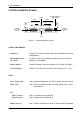
PANEL COMPONENTS
LAN Port - Reserved for future LAN port option (for web-based enclosure
management)
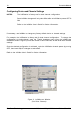
RS-232 Serial Port - Connection used for InfoStation external monitoring and con-
(Mini USB) figuration (via InfoMon)
Reset Switch - Resets InfoStation controller board (will not reset SCSI Bus)
I/O Connectors - VHDCI connectors used for SCSI host channels (Ch. 1 & 2)
LEDS
Over Temp (Red) - ON = Chassis temperature over 50
o
C (buzzer will also sound)
Fault (Red) - ON = One or more fault conditions (Power Supply, Fan, or Over
Temperature)
On:
Fan A (Amber) - ON = Fan Module A is operational
Fan B (Amber) - ON = Fan Module B is operational
Ready (Amber) - ON = Chassis is powered on and no fault conditions detected
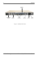
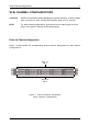
CONTROLLER MODULE PANEL
Figure 4: Controller Module Panel
VHDCI
Connectors
(Ch. 2)
LAN
Port
VHDCI
Connectors
(Ch. 1)
CH. 1 (IN)
CH. 1 (OUT)
CH. 2 (IN)
CH. 2 (OUT)
Over
Temp
Fault
Fan B
Fan A
Ready
RST
100
Mbps
Activity
Link
Fan A
Fan B
Dual Ch
Config
RS-232
(InfoMon)
SCSI LVD
ULTRA320
LAN Port
On LAN Port Fault
LEDs LEDs
RS-232 Serial Port
(Mini USB)
Reset