StorCase® Technology InfoStation® 14-Bay 2Gbps Fibre Channel External Expansion Chassis User's Guide
i StorCase® Technology InfoStation® 14-Bay 2Gbps Fibre Channel External Expansion Chassis User's Guide Part No. D89-0000-0210 B00 October 2003 StorCase Technology, Inc. 17600 Newhope Street Fountain Valley, CA 92708-9885 Phone (714) 438-1850 Fax (714) 438-1847 InfoStation 14-Bay FC User's Guide - Rev. B00 StorCase Technology, Inc.
ii LIMITED WARRANTY STORCASE TECHNOLOGY, Incorporated (StorCase) warrants that its products will be free from defects in material and workmanship, subject to the conditions and limitations set forth below. StorCase will, at its option, either repair or replace any part of its product that proves defective by reason of improper workmanship or materials.
iii Free Technical Support StorCase provides free technical support. If you experience any difficulty during the installation or subsequent use of a StorCase product, please contact StorCases Technical Support Department prior to servicing your system. This warranty covers only repair or replacement of defective StorCase products, as described above. StorCase is not liable for, and does not cover under warranty, any costs associated with servicing and/or installation of StorCase products.
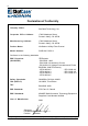
iv Declaration of Conformity Company Name: StorCase Technology, Inc.
v Federal Communications Commission (FCC) Statement RADIO FREQUENCY INTERFERENCE STATEMENT You are cautioned that changes or modifications not expressly approved by the party responsible for compliance could void your authority to operate that equipment. This device complies with part 15 of the FCC rules.
vi Table of Contents INTRODUCTION ..................................................................................................................... Packaging Information .................................................................................................. Serial Number ................................................................................................................ General Description ...........................................................................................
vii List of Figures Figure 1: Figure 2: Figure 3: Figure 4: Figure 5: Figure 6: Figure 7: Figure 8: Figure 9A: Figure 9B: Figure 10: Figure 11: Figure 12: Figure 13: Figure 14: Figure 15: Figure 16: Figure 17: InfoStation 14-Bay FC Chassis ..................................................................... 2 InfoStation Front Panel ................................................................................... 4 InfoStation Rear Panel .................................................................
viii List of Tables Table 1: Drive Carrier Interface Components ................................................................... 9 NOTICE: This User's Guide is subject to periodic updates without notice. While reasonable efforts have been made to ensure accuracy of this document, Storcase Technology, Inc. assumes no liability resulting from errors or omissions in this publication, or from the use of the information contained herein. Please check the StorCase web site at http://www.storcase.
Introduction 1 INTRODUCTION CAUTION: The InfoStation contains NO USER SERVICEABLE parts inside the unit. Refer ALL servicing to qualified service personnel! This unit has more than one power supply cord. Disconnect two power supply cords before servicing to avoid electric shock. NOTES: The installation, configuration, and use of the StorCase InfoStation chassis requires a certain level of expertise and experience on the part of the user/ integrator.
2 Introduction General Description The StorCase® Technology InfoStation® intelligent 3U rack-mount expansion chassis is designed to support the latest high-density, high-speed 2Gbps/1Gbps Fibre ChanneI disk drive technologies for use in network server, fault-tolerant and/or mission-critical applications. The InfoStation is designed to support 3.5" form factor, low profile (1" high) Fibre Channel drives.
Introduction 3 The latest versions of the InfoMon utility program and User's Guide can be downloaded (free of charge) from the StorCase web site (http://www.storcase.com). Contact StorCase for further information. Refer to Appendix B for further information on optional InfoStation accessories. Using a modular approach supported by redundant features and hot swapping capabilities, the InfoStation will provide continued data availability and allow for ease of maintenance and minimal system down time.
4 Introduction Front Panel (Figure 2) LED Indicator and Control Panel - LED panel displays system statuses, alarms, and warnings. Refer to section "InfoStation User Interface" for further information. SCA Drive Carrier(s) - Accommodate up to fourteen (14) 3.5" low-profile Fibre Channel devices. Backplane design with direct-connect SCA connectors eliminates cable connections to FC drives, increases data integrity, and supports drive hot swappability.
Introduction 5 Rear Panel (Figure 3) NOTE: Blank plate (provided) must be installed if any module slot is left empty. Installation of the blank plate is necessary for proper cooling inside chassis. Port Bypass Module "A" (Figure 4) - InfoStation comes equipped with one (1) Port Bypass (PBP) Module, for dual FC loop configurability. Port Bypass Module "B" Option - Allows the installation of an optional PBP Module, for quad loop configurability. Refer to Appendix B for further information.
6 Introduction Power Supply Module #2 Blower Vent Port Bypass Module A Power Supply Module #1 Power Supply Handle 14FC_03 Captive Screw A/C Power In Power Switch Module Option Port Bypass Module B Option Power Supply Module LEDs Figure 3: InfoStation Rear Panel (Dual Power Supply/Blower Module Version shown) Loop B Out In Loop A Out In LEDs PBP Module Handle 14FC_04 Locking Thumbscrew SFP Cages HSSDC2 SFP Module (Optional) Figure 4: Port Bypass Module StorCase Technology, Inc.
User Interface 7 INFOSTATION USER INTERFACE LED Indicator and Control Panel Each InfoStation provides the user with a visual indication of chassis configurations and communication statuses, in addition to providing an RS-232 connection for system environmental monitoring, configuration, and control (Figure 5).
8 User Interface Bypass - ON = One or more drives are being bypassed Reset - Resets InfoStation User Interface Module (will not reset FC loops) RS-232 Serial Port - RS-232 serial connection used for InfoStation external monitoring and configuration RA Com - Factory Reserved RB Com - Factory Reserved Select Button - Factory Reserved StorCase Technology, Inc. InfoStation 14-Bay FC User's Guide - Rev.
User Interface 9 Drive Carrier Interface Panel Each InfoStation drive carrier provides a User interface for individual carrier operation. LEDs Drive Ready Drive Activity Drive Fault Key Lock Carrier Handle IFS14_3 Figure 6: InfoStation Drive Carrier Interface The Drive Carrier Interface consists of the following indicators: Table 1: Drive Ready LED Drive Carrier Interface Components Steady glow indicates that drive is inserted and ready for access.
10 User Interface Inserting a Drive Carrier (with Drive Installed) NOTES: A new drive can be inserted into an empty bay at anytime. However, the drive will not be ready for access until the following procedure is followed. The key lock is only to prevent unauthorized removal or installation of the drive carrier. Locking the key lock is not required for drive carrier operation. 1. Simply insert the drive carrier into the empty bay. . 2. Drive is ready to be accessed when the Drive Ready LED glows.
Fibre Channel Configurations 11 FIBRE CHANNEL CONFIGURATIONS Port Bypass (PBP) Module CAUTION: DO NOT bend the LC (optical) cable beyond the cable's minimum bend radius, data transmission degradation may occur. Follow cable manufacturer's guidelines for bend radius limitation.
12 Fibre Channel Configurations DIAG All Bypass Loop A Data In Error Loop A Data Out Error Loop B Data In Error Loop B Data Out Error Figure 8: PBP Module LEDs PBP Module LEDs DIAG ON = OFF = Communication link to UI has failed Normal operation All Bypass ON = All drives are forced into bypass Loop A Data In Error ON = Error detected in the Loop A data input Loop A Data Out Error ON = Error detected in the Loop A data output Loop B Data In Error ON = Error detected in the Loop B data
Fibre Channel Configurations 13 SFP Module and Cable Installation CAUTION: DO NOT bend the LC (optical) cable beyond the cable's minimum bend radius, data transmission degradation may occur. Follow cable manufacturer's guidelines for bend radius limitation. WARNING: DO NOT look directly into the open end of an active LC (optical) cable or optical SFP module (with plugs removed)! Serious eye damage can occur from direct exposure to the infrared light! NOTES: SFP Module is hot-swappable.
14 Fibre Channel Configurations Figure 9A: Installing the LC (optical) SFP Module into the PBP Module Figure 9B: Installing the HSSDC2 (copper) SFP Module into the PBP Module StorCase Technology, Inc. InfoStation 14-Bay FC User's Guide - Rev.
Fibre Channel Configurations 2. 15 Remove the SFP plugs (Figure 9A) and install the cables into the SFP Modules (Figure 10). Make sure to remove any cable plugs from the cables prior to installation (if necessary).
16 Fibre Channel Configurations 3. To remove SFP Module from PBP Module, remove any cables installed in the SFP Module. For Optical SFP Modules, lower the Release Lever and pull the SFP Module from PBP Module (Figure 11). For HSSDC2 SFP Modules, squeeze the Release Tab while pulling the SFP Module from the PBP Module.
Fibre Channel Configurations 17 FC Loop and Speed Configuration NOTES: Factory default configuration is Dual Loop at 2Gbps. Refer to the InfoMon User's Guide for further information. If necessary, use InfoMon to change any factory default device or chassis settings. refer to the InfoMon User's Guide for further information.
18 Fibre Channel Configurations TYPICAL FIBRE CHANNEL CONFIGURATIONS NOTES: The installation, configuration, and use of the StorCase InfoStation chassis requires a certain level of expertise and experience on the part of the user/ integrator. Since there are many configuration options and variables (ie. host platforms, applications, etc), only general/typical configuration guidelines will be discussed in this User's Guide.
Fibre Channel Configurations NOTES: 19 Auto Loopback is enabled when there are no SFP Modules installed in the open Host ports. SFP modules are optional. Contact StorCase for further ordering information. FC-AL #1 Up to 9 InfoStations or 126 FC Drives maximum. FC HBA Host 0 = No SFP Module Installed (Auto Loopback) PC = SFP Module Installed Figure 13: Typical Single 14-Device Loop Configuration (Multiple Chassis) InfoStation 14-Bay FC User's Guide - Rev. B00 StorCase Technology, Inc.
20 Fibre Channel Configurations NOTES: Auto Loopback is enabled when there are no SFP Modules installed in the open Host ports. SFP modules are optional. Contact StorCase for further ordering information. Up to 9 InfoStations or 126 FC Drives maximum. FC-AL #1 For redundant loop configurations, make sure your O/S supports disk duplexing/mirroring. Refer to O/S manufacturers documentation for further information.
Fibre Channel Configurations NOTES: 21 Auto Loopback is enabled when there are no SFP Modules installed in the open Host ports. SFP modules are optional. Contact StorCase for further ordering information. FC-AL #2 FC-AL #1 Up to 9 InfoStations or 126 FC Drives maximum FC HBA Host 1 FC HBA Host 0 = No SFP Module Installed (Auto Loopback) PC PC = SFP Module Installed Figure 15: Typical Dual 7-Device Loops Configuration InfoStation 14-Bay FC User's Guide - Rev. B00 StorCase Technology, Inc.
22 Fibre Channel Configurations NOTES: Auto Loopback is enabled when there are no SFP Modules installed in the open Host ports. SFP modules are optional. Contact StorCase for further ordering information. Up to 9 InfoStations or 126 FC Drives maximum. FC-AL #1 FC-AL #2 For redundant loop configurations, make sure your O/S supports disk duplexing/mirroring. Refer to O/S manufacturers documentation for further information.
Fibre Channel Configurations NOTES: 23 Auto Loopback is enabled when there are no SFP Modules installed in the open Host ports. SFP modules are optional. Contact StorCase for further ordering information.
24 Fibre Channel Configurations This Page Left Blank Intentionally. StorCase Technology, Inc. InfoStation 14-Bay FC User's Guide - Rev.
Appendix A - Specifications/Dimensions 25 APPENDICES InfoStation 14-Bay FC User's Guide - Rev. B00 StorCase Technology, Inc.
26 Appendix A - Specifications/Dimensions Appendix A - Specifications/Dimensions The following InfoStation specifications and dimensions are provided for reference only.
Appendix A - Specifications/Dimensions 27 StorCase InfoStation Fibre Channel Rack Mount Enclosure 14 Bay # of BaySupported 14 # of Drive Carriers Included 14 Max. # of Drives Supported 14 Max. Storage Capacity 2.
28 Appendix A - Specifications/Dimensions StorCase InfoStation Fibre Channel Rack Mount Enclosure External Monitoring Utility via RS-232 Port Power-On-Hour (POH) Monitoring Yes Yes Audible Alarm Yes Standard 19 Rack-Mount Height = 3U Technical Support Toll-Free Limited Warranty 7 Years* Regulatory Approvals EMI Safety Agency FCC/CE/C-tick CSA/CSA US/TUV * 3 year limited warranty on Power & Cooling Modules. StorCase Technology, Inc. InfoStation 14-Bay FC User's Guide - Rev.
Appendix A - Specifications/Dimensions 29 16.92 (429.8mm) 20.57 (522.5mm) Top View Front View Right Side View 5.21 (132.3mm) 18.98 (482.1mm) 20.98 (532.9mm) 14FC_dims Figure A-1: InfoStation Physical Dimensions (Dimensions are for reference only) InfoStation 14-Bay FC User's Guide - Rev. B00 StorCase Technology, Inc.
30 Appendix B - Optional Accessories Appendix B - Optional Accessories Port Bypass Module The InfoStation's scalable backplane design allows additional modules to be offered, supporting a variety of FC configurations. An additional PBP module (P/N S10D107) is available to upgrade the InfoStation for quad loop applications. Contact StorCase for further ordering information. 14FC_12 Figure B-1: PBP Module StorCase Technology, Inc. InfoStation 14-Bay FC User's Guide - Rev.
Appendix B - Optional Accessories 31 SFP Modules HSSDC2 (Copper) SFP Module (P/N S10D108) 14FC_14 Figure B-2: HSSDC2 (Copper) SFP Modules LC (Optical) SFP Module (P/N S10D114) 14FC_15 Figure B-3: LC (Optical) SFP Modules InfoStation 14-Bay FC User's Guide - Rev. B00 StorCase Technology, Inc.
32 Appendix B - Optional Accessories Patch Cable Kit (P/N S90D100) Figure B-4: Patch Cable Kit StorCase Technology, Inc. InfoStation 14-Bay FC User's Guide - Rev.
Appendix B - Optional Accessories 33 Slide Rail Kit The optional slide rail kit (P/N DXRCK-SLIDE) provides a convenient method to attach the InfoStation to a rack mount enclosure (Figure B-5). These high quality, durable rails provide 24 ball bearing rollers and have a quick-release button which allows quick and easy installation and removal of the InfoStation unit from its rack enclosure. Contact StorCase for further ordering information.
34 Appendix B - Optional Accessories Optional Power Supply/Blower Module CAUTION: The power supply/blower module contains NO USER SERVICEABLE PARTS inside the unit. Warranty is VOID if module is opened. Refer ALL servicing to qualified service personnel! NOTE: Refer to the InfoStation Installation Guide for further information. An optional second 650W power supply module (P/N S10D109) is available for the InfoStation chassis as shown in Figure B-6. Contact StorCase for further ordering information.
Appendix B - Optional Accessories 35 Drive Carrier Spare drive carriers (P/N S10A116) are available for the InfoStation chassis as shown in Figure B-7. Contact StorCase for further ordering information. IFS14_25 Figure B-7: Drive Carrier InfoStation 14-Bay FC User's Guide - Rev. B00 StorCase Technology, Inc.
36 Appendix B - Optional Accessories Carrying Case (Figure B-8) The optional molded plastic carrying case (P/N S20E104) is designed to transport the InfoStation drive carrier from one site to another in a safe, impact and moisture resistant environment. Its compact dimensions, 7" long x 9" wide x 4" high, make it easy to carry and store. The foam lining is contoured to fit a single InfoStation carrier. Contact your StorCase dealer for further details and ordering information.
Appendix B - Optional Accessories 37 Rack-to-Tower Conversion Kit This kit (P/N S10E100) provides all the parts necessary to convert an existing rack mount InfoStation to a tower conversion as shown in Figure B-9. Contact StorCase for further ordering information. Pan Hd. Screw (1 Total) Top Cover Pan Hd. Screw (4 Total) Top Cover Base Left Cover Hex Nut* (4 Total) Right Cover Bezel* F.H. Screw (1 per Side) F.H. Screw* (4 Total) Base Pan Hd.
38 Appendix B - Optional Accessories InfoStation Monitoring Utility (InfoMon®) InfoMon is a web-based monitoring utility that runs under the Windows O/S. This free utility (and its accompanying User's Guide) is available for download at the StorCase web site (http://www.storcase.com). The primary purpose of InfoMon is to continuously monitor the environmental status and indicate alarm conditions inside the InfoStation chassis via a serial connection to a PC.
Reader's Comments 39 Reader's Comments Please take a few moments when your computer system is up and running to send us your ideas and suggestions for improving our products and documentation.
Reader's Comments CUT ALONG THIS LINE FROM BOTTOM TO TOP OF PAGE 40 FOLD ALONG THIS LINE AND STAPLE SHUT NO POSTAGE NECESSARY IF MAILED IN THE UNITED STATES B U S I N E S S R E P LY M A I L FIRST CLASS MAIL PERMIT NO. 10686 SANTA ANA, CA POSTAGE WILL BE PAID BY ADDRESSEE TECHNOLOGY CORPORATION 17600 NEWHOPE STREET FOUNTAIN VALLEY CA 92708-9885 StorCase Technology, Inc. InfoStation 14-Bay FC User's Guide - Rev.