StorCase® Technology InfoStation External SCSI Expansion Chassis Installation Guide
i StorCase® Technology InfoStation External SCSI Expansion Chassis Installation Guide Part No. D89-0000-0112 C01 August 2001 StorCase Technology, Inc. 17600 Newhope Street Fountain Valley, CA 92708-9885 Phone (714) 438-1850 Fax (714) 438-1847 InfoStation Installation Guide - Rev. C01 StorCase Technology, Inc.
ii Important Safety Instructions 1. Read all these instructions. 2. Save these instructions for later use. 3. Follow all warnings and instructions marked on the product. 4. Do not use this product near water. 5. This product should be operated from the type of power source indicated on the marking label. If you are not sure of the type of power available, consult your dealer or local power company. 6.
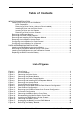
iii Table of Contents INFOSTATION INSTALLATION ............................................................................................. 1 Installing the Drive(s) into the InfoStation ................................................................... 1 Drive Preparation .................................................................................................. 1 Removing a Drive Carrier (without a Drive Installed) .........................................
iv NOTICE: This User's Guide is subject to periodic updates without notice. While reasonable efforts have been made to ensure accuracy of this document, StorCase Technology, Inc. assumes no liability resulting from errors or omissions in this publication, or from the use of the information contained herein. Please check the StorCase web site at http://www.storcase.com or contact your StorCase representative for the latest revision of this document. StorCase Technology, Inc.
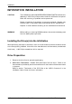
Installation 1 INFOSTATION INSTALLATION CAUTION: The InfoStation contains NO USER SERVICEABLE PARTS inside the unit. Warranty is VOID if any of the modules inside the InfoStation are opened. Refer ALL servicing to qualified service personnel! Danger of explosion if the battery is incorrectly replaced! Replace only with the same or equivalent type recommended by the manufacturer. Dispose of used batteries according to the manufacturer'sinstructions.
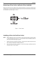
2 Installation Removing a Drive Carrier (without a Drive Installed) Remove the drive carrier by grasping carrier handle and pushing in the carrier release button simultaneously. Pushing in the carrier release button will unlock carrier and allow removal from the InfoStation drive bay (Figure 1 and 3). Figure 1: Drive Carrier Installing a Drive into the Drive Carrier NOTE: Before installing the drive into the carrier, the ID jumpers and spin-up option jumper on the disk drive must be removed.
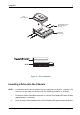
Installation 3 Drive (Not Included) #6-32 Phillips Head Mounting Screw (4 total) InfoStation Drive Carrier IFS_18 Figure 2: Drive Installation Inserting a Drive into the Chassis NOTE: A new drive carrier can be inserted into an empty bay at anytime. However, the drive will not be ready for access until the following procedure is followed. 1. Press and hold the Insert/Remove button in until the Drive Ready LED starts to flash (approximately 3 seconds). 2.
4 Installation Removing a Drive from the Chassis (Refer to section "Drive Bay Interface Panel" in the InfoStation User's Guide for further information) NOTE: Proper procedure must be followed when removing a drive from the drive bay. It is the responsibility of the User to ensure that the host does not access the drive while attempting to remove the drive, and to follow the procedure outlined below. Failure to do so may result in loss of data and/or damage to the drive itself! 1.
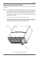
Installation 5 Removing the Blower Module CAUTION: The blower module contains NO USER SERVICEABLE PARTS inside the unit. Warranty is VOID if module is opened. Refer ALL servicing to qualified service personnel! NOTE: The blower module is hot-swappable. The chassis may remain on when removing and installing the blower module. 1. Loosen and remove the #6-32 Phillips Pan Head screw securing the blower module to the InfoStation chassis (Figure 4). 2.
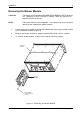
6 Installation Removing the Power Supply Module CAUTION: The power supply module contains NO USER SERVICEABLE PARTS inside the unit. Warranty is VOID if module is opened. Refer ALL servicing to qualified service personnel! NOTE: The power supply module is hot-swappable. The chassis may remain on when removing and installing the power supply module. 1. Turn OFF power to the power supply module via the Power Switch located on the module itself. 2.
Installation 7 Removing and Installing the I/O Repeater Module CAUTION: Remove ALL power from the InfoStation before removing the I/O repeater module. The I/O repeater module contains NO USER SERVICEABLE PARTS inside the unit. Refer ALL servicing to qualified service personnel! NOTE: The I/O repeater module is NOT hot-swappable! Remove ALL power to chassis before removing and installing the I/O repeater module. 1. Unplug the InfoStation and verify that all cables have been disconnected. 2.
8 Installation Removing the InfoStation Access Panel CAUTION: Remove ALL power from the InfoStation before removing the access panel(s). The InfoStation contains NO USER SERVICEABLE PARTS inside the unit. Warranty is VOID if any of the modules inside the InfoStation are opened. Refer ALL servicing to qualified service personnel! 1. Unplug the InfoStation and verify that all cables have been disconnected. 2. Place the InfoStation on a soft clean surface to protect finish of the chassis. 3.
Installation 9 Figure 8 below shows the inside of the InfoStation chassis (single-channel configuration) with the access panel removed. Figure 8: Single-Channel Configuration InfoStation Installation Guide - Rev. C01 StorCase Technology, Inc.
10 Installation Configuring the InfoStation for Dual-Channel CAUTION: Remove ALL power from the InfoStation before removing the I/O repeater module. The I/O repeater module contains NO USER SERVICEABLE PARTS inside the unit. Refer ALL servicing to qualified service personnel! 1. Unplug the InfoStation and verify that all cables have been disconnected. 2. Place the InfoStation on a soft clean surface to protect finish of the chassis. 3.
Installation 11 Figure 10: Dual-Channel Configuration InfoStation Installation Guide - Rev. C01 StorCase Technology, Inc.
12 Installation Configuring the InfoStation for 4-Channel CAUTION: Remove ALL power from the InfoStation before removing the I/O repeater module. The I/O repeater module contains NO USER SERVICEABLE PARTS inside the unit. Refer ALL servicing to qualified service personnel! 1. Unplug the InfoStation and verify that all cables have been disconnected. 2. Place the InfoStation on a soft clean surface to protect finish of the chassis. 3.
Installation 13 Figure 12: 4-Channel Configuration InfoStation Installation Guide - Rev. C01 StorCase Technology, Inc.
14 Installation RAID MODULE INSTALLATION CAUTION: Remove ALL power from the InfoStation before installing the RAID Module. The RAID Module contains NO USER SERVICEABLE PARTS inside the unit. Warranty is VOID if module is opened. Refer ALL servicing to qualified service personnel! NOTES: The installation, configuration, and use of the RAID module option for the StorCase InfoStation chassis requires a certain level of expertise and experience on the part of the user/integrator.
Installation 15 InfoStation Chassis (Rear) IFS_43 #6-32 Phillips Head Screw (3 per Plate) Module Option Cover Plate Figure 13: Removing the Module Option Cover Plate Save this Section! Module Option Cover Plate IFS_44 #6-32 Phillips Head Screw (1 Place) Figure 14: Disassembling the Module Option Cover Plate InfoStation Installation Guide - Rev. C01 StorCase Technology, Inc.
16 Installation Installing the RAID Module into the InfoStation Chassis 1. Carefully slide the RAID module into the chassis and tighten screws (Figure 15). 2. Attach the smaller section of the disassembled cover plate to the module and chassis and secure with two (2) #6-32 Phillips Head screws (Figure 15). DXIFS_45 InfoStation Chassis (Rear) DXIFS-160/RAID Controller Module #6-32 Phillips Head Screw (2 Places) Figure 15: Installing the RAID Module into the Chassis StorCase Technology, Inc.
Installation 17 Replacing the RAID Controller Battery CAUTION: Remove ALL power from the InfoStation before uninstalling the RAID Module. The RAID Module contains NO USER SERVICEABLE PARTS inside the unit (only the battery is user serviceable). Warranty is VOID if module is opened (only the battery cover may be opened by user).
18 Installation 3. Once the battery cover is removed, unplug the battery cable from the RAID module (Figure 17). 4. Carefully turn the RAID Module over to access the two (2) screws securing the battery bracket to the module (Figure 18). Loosen and remove the screws. The bracket and battery should now drop out when the RAID Module is lifted. Battery Cable 3-Cell NiMH Battery Disconnect Cable Here IFS_74 Figure 17: Unplugging the Battery from the RAID Module 5.
Installation 19 Battery Bracket E D/S LV SI SC 60 A1 TR UL IFS_73 3-Cell NiMH Battery Remove These Two Screws Figure 18: Removing the Battery Bracket InfoStation Installation Guide - Rev. C01 StorCase Technology, Inc.