StorCase® Technology InfoStation® External SCSI Expansion Chassis User's Guide
i StorCase® Technology InfoStation® External SCSI Expansion Chassis User's Guide Part No. D89-0000-0104 A01 January 2003 StorCase Technology, Inc. 17600 Newhope Street Fountain Valley, CA 92708-9885 Phone (714) 438-1850 Fax (714) 438-1847 InfoStation User's Guide - Rev. A01 StorCase Technology, Inc.
ii LIMITED WARRANTY STORCASE TECHNOLOGY, Incorporated (StorCase) warrants that its products will be free from defects in material and workmanship, subject to the conditions and limitations set forth below. StorCase will, at its option, either repair or replace any part of its product that proves defective by reason of improper workmanship or materials.
iii Free Technical Support StorCase provides free technical support. If you experience any difficulty during the installation or subsequent use of a StorCase product, please contact StorCases Technical Support Department prior to servicing your system. This warranty covers only repair or replacement of defective StorCase products, as described above. StorCase is not liable for, and does not cover under warranty, any costs associated with servicing and/or installation of StorCase products.
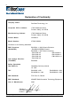
iv Declaration of Conformity Company Name: StorCase Technology, Inc.
v Federal Communications Commission (FCC) Statement RADIO FREQUENCY INTERFERENCE STATEMENT You are cautioned that changes or modifications not expressly approved by the party responsible for compliance could void your authority to operate that equipment. This device complies with part 15 of the FCC rules.
vi Important Safety Instructions 1. Read all these instructions. 2. Save these instructions for later use. 3. Follow all warnings and instructions marked on the product. 4. Do not use this product near water. 5. This product should be operated from the type of power source indicated on the marking label. If you are not sure of the type of power available, consult your dealer or local power company. 6.
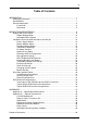
vii Table of Contents INTRODUCTION ..................................................................................................................... Packaging Information .................................................................................................. Serial Number ................................................................................................................ General Description ..........................................................................................
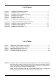
viii List of Figures Figure 1: Figure 2: Figure 3: Figure 4: Figure 5: Figure 6: Figure 7: InfoStation (Rack Mount Version) ................................................................. 2 InfoStation (Tower Version) ......................................................................... 3 InfoStation Drive Installation Overview ......................................................... 4 InfoStation Front Panel ...................................................................................
Introduction 1 INTRODUCTION CAUTION: The InfoStation contains NO USER SERVICEABLE parts inside the unit. Refer ALL servicing to qualified service personnel! Packaging Information The StorCase Technology InfoStation external expansion chassis is shipped in a container designed to provide protection and prevent damage during shipment. The InfoStation was carefully inspected before and during the packing procedure at the factory.
2 Introduction General Description The StorCase ® Technology InfoStation ® intelligent expansion chassis is designed to support the latest high-density, high-speed SCSI disk drive technologies for use in network server, fault tolerant and/or mission-critical applications. The InfoStation is designed to support 3.5" form factor, half-height, and low profile (1" high) SCSI Single-Ended (S.E.) and Ultra2 (LVD)/S.E. devices.
Introduction 3 Figure 2: InfoStation (Tower Version) Using a modular approach supported by redundant features and hot swapping capabilities, the InfoStation will provide continued data availability and allow for ease of maintenance and minimal system down time.
4 Introduction Features: - Nine (9) removable drive carriers 16-Bit SCSI Single-Ended or Ultra2 drive support Scalable backplane design Corrosion-resistant steel construction Four (4) hot-swappable blowers Two (2) 400W hot-swappable power supplies Eight-Character scrolling display and control panel Audible alarm Status indicators at each bay External monitoring utility 7-year warranty and free technical support Figure 3: InfoStation Drive Installation Overview StorCase Technology, Inc.
Introduction 5 Front Panel (Figure 4) User Interface Module (UIM) - Provides control of drive set-up options while the 8-character LED panel displays system statuses, alarms, and warnings. Refer to section "INFOSTATION USER INTERFACE" for further information. SCA Drive Carrier(s) - Accommodate up to nine (9) 3.5" single-connect SCSI devices. Backplane design with direct-connect SCA connectors eliminates cable connections to SCSI drives, increases data integrity, and supports drive hot swappability.
6 Introduction Rear Panel (Figure 5) Ultra2 (LVD) I/O Repeater Module(s) - Enhances drive signal quality. Additional I/O repeater modules are optional, for a total of four (4) LVD channels. Refer to Appendix B for further information. Repeater Module LED(s) Error LED (Amber) - Flashing indicates a detection in either: 1. Over temperature 2. Low termination voltage 3.
Introduction 7 Power Supply Module(s) - Two (2) 400W redundant, hot swappable power supply modules. Each module features overvoltage and overcurrent protection, total usage hours, and power supply fault detection. Power Supply Module LED(s) Green LED - Steady glow indicates normal power supply operation. No glow indicates no A/C power or abnormal DC voltage range. Red LED - Flashing indicates temperature or over/undervoltage conditions.
8 InfoStation User Interface INFOSTATION USER INTERFACE The StorCase InfoStation is an intelligent external expansion chassis. Each InfoStation is equipped with a comprehensive User Interface which provides chassis status based on several internal environmental sensors. This section describes the InfoStation User Inter- face features and functions. The User Interface has two (2) main functions: 1. To display the enclosure's environmental status and indicate alarm conditions 2.
InfoStation User Interface Table 1: NOTE: 9 Display and Control Panel Components Alarm conditions cannot be reset! An alarm condition will automatically reset when the status of the failed component returns to normal. InfoStation User's Guide - Rev. A01 StorCase Technology, Inc.
10 InfoStation User Interface The User Interface Module (together with the drive bay, blower, power supply, and repeater modules) provides the following enclosure monitoring and control capabilities: 1. Temperature sensor readings at the: drive bays, power supply modules, repeater modules, blower modules, and the ambient temperature immediately outside of the InfoStation 2. Power supply status 3. Blower module status 4. Buzzer enable/disable 5.
InfoStation User Interface 11 InfoStation Menu System The menu system navigation is done using the Enter, Cancel, Up, and Down switches. The following table describes the specific function of each navigation button. Table 2: InfoStation Menu Navigation Switches The first menu level is entered when the Enter button is pushed at the Default Display. Only one menu item of a particular menu level can be displayed at one time. InfoStation User's Guide - Rev. A01 StorCase Technology, Inc.
12 InfoStation User Interface InfoStation Environmental Information and Set-Up Power Supply Status The following steps show how to access InfoStation power supply module status information. NOTE: NOTE: Press CANCEL at anytime to exit the menu system and return to the Default Display. The menu system will automatically cancel after 15 seconds of User inactivity. 1. Press ENTER at the Default Display so that display = Status. 2. Press ENTER again until display = Temp. 3.
InfoStation User Interface 13 Blower Module Status The following steps show how to access InfoStation blower module status information. NOTE: NOTE: Press CANCEL at anytime to exit the menu system and return to the Default Display. The menu system will automatically cancel after 15 seconds of User inactivity. 1. Press ENTER at the Default Display so that display = Status. 2. Press ENTER again until display = Temp. 3. Press DOWN until display = Fan. 4.
14 InfoStation User Interface Repeater Module Status The following steps show how to access InfoStation repeater module status information. NOTE: NOTE: Press CANCEL at anytime to exit the menu system and return to the Default Display. The menu system will automatically cancel after 15 seconds of User inactivity. 1. Press ENTER at the Default Display so that display = Status. 2. Press ENTER again until display = Temp. 3. Press DOWN until display = Repeater. 4.
InfoStation User Interface 15 Temperature Readings The following steps show how to access InfoStation drive bay temperature information. NOTE: NOTE: Press CANCEL at anytime to exit the menu system and return to the Default Display. The menu system will automatically cancel after 15 seconds of User inactivity. 1. Press ENTER at the Default Display so that display = Status. 2. Press ENTER again until display = Temp. 3. Press ENTER again until display = BAY1:xxC.
16 InfoStation User Interface Firmware Revision The following steps show how to access InfoStation firmware revision information. NOTE: NOTE: Press CANCEL at anytime to exit the menu system and return to the Default Display. The menu system will automatically cancel after 15 seconds of User inactivity. 1. Press ENTER at the Default Display so that display = Status. 2. Press ENTER again until display = Temp. 3. Press DOWN until display = F/W Rev. 4. Press ENTER until display = V x.x.xx.
InfoStation User Interface 17 System Error Status The following steps show how to view InfoStation error conditions. NOTE: Press CANCEL at anytime to exit the menu system and return to the Default Display. 1. Press ENTER at the Default Display so that display = Status. 2. Press DOWN until display = Error. 3. Press ENTER and any errors present will be displayed. Press Up or Down to scroll through the error list. If no error is present, then display will read "No Error".
18 InfoStation User Interface Drive Bay SCSI ID Configuration Although the InfoStation will operate properly without the Display and Control Panel, no status will be reported, and the drive bay SCSI IDs must be configured as follows: - If a drive bay's SCSI ID has not been configured previously, the SCSI ID will default to the values listed in Table 3 below. - If a drive bay's SCSI ID has been configured previously, the configured SCSI ID will be assumed.
InfoStation User Interface 19 The following steps show how to set-up the drive bay SCSI ID via the Display and Control Panel. NOTE: NOTE: Press CANCEL at anytime to exit the menu system and return to the Default Display. The menu system will automatically cancel after 15 seconds of User inactivity. 1. Press ENTER at the Default Display so that display = Status. 2. Press DOWN until display = Bay Cfg. 3. Press ENTER until display = SCSI ID. 4. Press ENTER again until display = BAY1:0.
20 InfoStation User Interface Spin-Up Option Set-Up The following steps show how to change the InfoStation drive bay spin-up option. NOTE: NOTE: Press CANCEL at anytime to exit the menu system and return to the Default Display. The menu system will automatically cancel after 15 seconds of User inactivity. 1. Press ENTER at the Default Display so that display = Status. 2. Press DOWN until display = Bay Cfg. 3. Press ENTER until display = SCSI ID. 4. Press DOWN until display = Spin up. 5.
InfoStation User Interface 21 Table 4: Spin-Up Option Settings InfoStation User's Guide - Rev. A01 StorCase Technology, Inc.
22 InfoStation User Interface SAF-TE Module SCSI ID Set-Up The following steps show how to change the SAF-TE module SCSI ID. NOTE: NOTE: Press CANCEL at anytime to exit the menu system and return to the Default Display. The menu system will automatically cancel after 15 seconds of User inactivity. 1. Press ENTER at the Default Display so that display = Status. 2. Press DOWN until display = SAFT Cfg. 3. Press ENTER until display = SCSI ID. 4. Press ENTER again until display = SAFT1:xx.
InfoStation User Interface 23 Enabling/Disabling the Buzzer The following steps show how to enable/disable the InfoStation alarm/warning buzzer. NOTE: Press CANCEL at anytime to exit the menu system and return to the Default Display. The menu system will automatically cancel after 15 seconds of User inactivity. 1. Press ENTER at the Default Display so that display = Status. 2. Press DOWN until display = Buzzer. 3. Press ENTER until display = BUZ=ON (or BUZ=OFF). This is the current buzzer setting.
24 InfoStation User Interface Temperature Alarm Level Set-Up The following steps show how to view and change the InfoStation temperature alarm warning and critical levels. NOTE: Press CANCEL at anytime to exit the menu system and return to the Default Display. The menu system will automatically cancel after 15 seconds of User inactivity. Warning Level StorCase Technology, Inc. 1. Press ENTER at the Default Display so that display = Status. 2. Press DOWN until display = Setup. 3.
InfoStation User Interface 25 Critical Level 1. Press ENTER at the Default Display so that display = Status. 2. Press DOWN until display = Setup. 3. Press ENTER until display = Alarm. 4. Press ENTER until display = Warn:xxC. 5. Press DOWN until display = Crit:xxC. This is the current critical temperature level (in degrees Celsius) at which the InfoStation will shut itself off. 6. Press ENTER until display = Crit=xxC. 7. Press UP or DOWN to change the critical level. 8.
26 InfoStation User Interface Enclosure ID Set-Up The following steps show how to view and change the InfoStation Enclosure ID. NOTE: Press CANCEL at anytime to exit the menu system and return to the Default Display. The menu system will automatically cancel after 15 seconds of User inactivity. StorCase Technology, Inc. 1. Press ENTER at the Default Display so that display = Status. 2. Press DOWN until display = Setup. 3. Press ENTER until display = Alarm. 4. Press DOWN until display = Enc. ID.
InfoStation User Interface 27 Serial Port Set-Up The following steps show how to view and change the InfoStation serial port option. NOTE: NOTE: Press CANCEL at anytime to exit the menu system and return to the Default Display. The menu system will automatically cancel after 15 seconds of User inactivity. 1. Press ENTER at the Default Display so that display = Status. 2. Press DOWN until display = Setup. 3. Press ENTER until display = Alarm. 4. Press DOWN until display = Ser.Port 5.
28 InfoStation User Interface Changing the Fan Speed The following steps show how to change the InfoStation fan speed. NOTE: Press CANCEL at anytime to exit the menu system and return to the Default Display. The menu system will automatically cancel after 15 seconds of User inactivity. StorCase Technology, Inc. 1. Press ENTER at the Default Display so that display = Status. 2. Press DOWN until display = Setup. 3. Press ENTER until display = Alarm. 4. Press DOWN until display = FanSpeed. 5.
InfoStation User Interface 29 Banner Set-Up The following steps show how to customize the InfoStation start-up banner. NOTE: Press CANCEL at anytime to exit the menu system and return to the Default Display. The menu system will automatically cancel after 15 seconds of User inactivity. 1. Press ENTER at the Default Display so that display = Status. 2. Press DOWN until display = Setup. 3. Press ENTER until display = Alarm. 4. Press DOWN until display = Banner. 5.
30 InfoStation User Interface Drive Bay Interface Panel Each InfoStation drive bay provides a User interface for individual bay operation. Drive Bay Drive Ready LED Bay Identify LED Drive Activity LED 1 Insert/Remove Push Button Drive Fault LED Figure 7: InfoStation Drive Bay Interface Panel The Drive Bay Interface Panel consists of the following indicators and buttons: Table 6: Drive Ready LED Drive Bay Interface Components Steady glow indicates that drive is inserted and ready for access.
InfoStation User Interface 31 Insert/Remove Push Button The operator must follow the procedures below to remove or insert a drive carrier (with drive installed) into the InfoStation drive bay. Inserting a Drive Carrier (with Drive Installed) NOTE: A new disk drive can be inserted into an empty bay at anytime. However, the drive will not be ready for access until the following procedure is followed. 1.
32 SCSI Channel Configurations SCSI CHANNEL CONFIGURATIONS Termination of the SCSI Bus at the VHDCI Connectors NOTES: Port-A1 and Port-A2 are connected internally. Port-A requires an external terminator if: a. It is connected to the end of an external SCSI cable. b. It is "open" and not in use. In this case, only Port B is used. Port-B is terminated internally. When using the double-stacked VHDCI connectors (Port A-1 & A-2) simultaneously, offset VHDCI cable connectors must be used for proper fit.
SCSI Channel Configurations 33 Typical Single SCSI Channel Configurations NOTE: Up to 15 drives maximum per SCSI channel. Example #1: Typical Single SCSI Host Connection to InfoStation SCSI Ch-1, Port-A1 Example #2: Typical SCSI Host Connection to InfoStation SCSI Ch-1, Port-A2 InfoStation User's Guide - Rev. A01 StorCase Technology, Inc.
34 SCSI Channel Configurations Example #3: Typical Single SCSI Host Connection to InfoStation SCSI Ch-1, Port-B Example #4: Typical Single SCSI Host Connection to Two InfoStations StorCase Technology, Inc. InfoStation User's Guide - Rev.
SCSI Channel Configurations 35 Example #5: Typical Single SCSI Host Connection to Two InfoStations Example #6: Typical Single SCSI Host Connection to Two InfoStations InfoStation User's Guide - Rev. A01 StorCase Technology, Inc.
36 SCSI Channel Configurations Typical Dual SCSI Channel Configurations NOTE: Up to 15 drives maximum per SCSI channel. Example #7: Typical Dual SCSI Host Connection to Two InfoStations StorCase Technology, Inc. InfoStation User's Guide - Rev.
Appendix A - Specifications/Dimensions 37 APPENDICES InfoStation User's Guide - Rev. A01 StorCase Technology, Inc.
38 Appendix A - Specifications/Dimensions Appendix A - Specifications/Dimensions The following InfoStation specifications and dimensions are provided for reference only. Environmental Specifications Operating Ambient Temperature Relative Humidity (1) 0° C to 50° C 10% to 80% -1000 to 50,000 ft -304m to 15240m 10g Altitude Shock (1) (2) (2) Non-condensing with maximum gradient of 10% per hour 11 msec pulse width 1/2 sine wave Physical Specifications Rack Mount Tower Height 6.95" (176.
Appendix A - Specifications/Dimensions 39 StorCase InfoStation IFS-9R-SWCU2 Base Model # of BaySupported 9 # of Drive Carriers Included 9 Max. # of Drives Supported 9 Max.
40 Appendix A - Specifications/Dimensions StorCase InfoStation IFS-9R-SWCU2 Base Model External Monitoring Utility via RS-232 Port Power-On-Hour (POH) Monitoring Yes Yes Audible Alarm Yes Standard 19 Rack-Mount Yes Height 4U Technical Support Toll-Free Warranty 7 Years Regulatory Approvals EMI Safety Agency FCC/CE/C-tick CSA/CSA US/TUV IFS_specs3 StorCase Technology, Inc. InfoStation User's Guide - Rev.
Appendix A - Specifications/Dimensions 41 16.92 (429.8mm) 20.57 (522.5mm) Front View Top View Right Side View 6.95 (176.5mm) 18.98 (482.1mm) 20.98 (532.89mm) IFS_9 Figure A-1: InfoStation Rack Mount Physical Dimensions (Dimensions are for reference only) InfoStation User's Guide - Rev. A01 StorCase Technology, Inc.
42 Appendix A - Specifications/Dimensions 8.47 (215.1mm) 21.04 (534.4mm) Top View Right Side View Front View 19.96 (507.0mm) 10.12 (257.0mm) 22.96 (583.2mm) IFS_10 Figure A-2: InfoStation Tower Physical Dimensions (Dimensions are for reference only) StorCase Technology, Inc. InfoStation User's Guide - Rev.
Appendix B - Optional Accessories 43 Appendix B - Optional Accessories LVD I/O Repeater Kit The InfoStation's scalable backplane design allows additional I/O repeater and terminator kits to be offered, supporting a variety of LVD drive-to-channel configurations. Additional optional interface/repeater kits (P/N DXIFS-RPTR-KIT) are available to upgrade the single and dualchannel models to a total of four (4) LVD channels. Each repeater kit comes with an I/O repeater module and terminator (Figure B-1).
44 Appendix B - Optional Accessories Rack-to-Tower Conversion Kit This kit (P/N DXIFS-TKIT) provides all the parts necessary to convert an existing rack mount InfoStation to a tower conversion (Figure B-2). Contact StorCase for further ordering information. InfoStation Chassis Left Cover Bracket Right Cover Bracket IFS_12 Figure B-2: InfoStation Rack-to-Tower Kit (DXIFS-TKIT) StorCase Technology, Inc. InfoStation User's Guide - Rev.
Appendix B - Optional Accessories 45 Slide Rail Kit The optional slide rail kit (P/N DXRCK-SLIDE) provides a convenient method to attach the InfoStation to a rack mount enclosure (Figure B-3). These high quality, durable rails provide 24 ball bearing rollers and have a quick release button which allows quick and easy installation and removal of the InfoStation unit from its rack enclosure. Contact StorCase for further ordering information.
46 Appendix B - Optional Accessories Replacement Power Supply Module A replacement 400W power supply module (P/N DXIFS-PS400) is available for the InfoStation chassis as shown in Figure B-4. Contact StorCase for further ordering information. IFS_14 Figure B-4: Power Supply Module (DXIFS-PS400) Replacement Blower Module A replacement blower module (P/N DXIFS-FAN) is available for the InfoStation chassis as shown in Figure B-5. Contact StorCase for further ordering information.
Appendix B - Optional Accessories 47 Drive Carrier Spare drive carriers (P/N DXIFS-SWCU2) are available for the InfoStation chassis as shown in Figure B-6. Contact StorCase for further ordering information. IFS_16 Figure B-6: Drive Carrier (DXIFS-SWCU2) InfoStation User's Guide - Rev. A01 StorCase Technology, Inc.
48 Appendix B - Optional Accessories InfoStation External Monitoring Utility (InfoMon®) The InfoStation is an external monitoring utility that runs under the Windows® O/S. This free utility (and its accompanying User's Guide) is available for download at the StorCase website (http://www.storcase.com). The primary purpose of this utility is to continuously monitor the environmental status and indicate alarm conditions inside the InfoStation chassis via a serial connection.
Reader's Comments 49 Reader's Comments Please take a few moments when your computer system is up and running to send us your ideas and suggestions for improving our products and documentation.
Reader's Comments CUT ALONG THIS LINE FROM BOTTOM TO TOP OF PAGE 50 FOLD ALONG THIS LINE AND STAPLE SHUT NO POSTAGE NECESSARY IF MAILED IN THE UNITED STATES B U S I N E S S R E P LY M A I L FIRST CLASS MAIL PERMIT NO. 10686 SANTA ANA, CA POSTAGE WILL BE PAID BY ADDRESSEE TECHNOLOGY CORPORATION 17600 NEWHOPE STREET FOUNTAIN VALLEY CA 92708-9885 StorCase Technology, Inc. InfoStation User's Guide - Rev.