StorCase® Technology InfoStation® 9-Bay SCSI Ultra320 External Expansion Chassis Installation Guide
i StorCase® Technology InfoStation® 9-Bay SCSI Ultra320 External Expansion Chassis Installation Guide Part No. D89-0000-0164 B00 October 2002 StorCase Technology, Inc. 17600 Newhope Street Fountain Valley, CA 92708-9885 Phone (714) 438-1850 Fax (714) 438-1847 InfoStation 9-Bay Installation Guide - Rev. B00 StorCase Technology, Inc.
ii Important Safety Instructions 1. Read all these instructions. 2. Save these instructions for later use. 3. Follow all warnings and instructions marked on the product. 4. Do not use this product near water. 5. This product should be operated from the type of power source indicated on the marking label. If you are not sure of the type of power available, consult your dealer or local power company. 6.
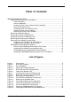
iii Table of Contents INFOSTATION INSTALLATION ............................................................................................. 1 Installing the Drive(s) into the InfoStation ................................................................... 1 Drive Preparation .................................................................................................. 1 Carrier Preparation ...............................................................................................
iv List of Figures (cont'd) Figure 17: Figure 18: Figure 19: Figure 20: Figure 21: Installing/Removing a Single-Channel RAID Controller Module .................. RAID Battery Backup Unit ............................................................................ Installation Location of RAID Battery Backup Unit ...................................... Installing the RAID Battery Backup Unit into the Blower Module ............... RAID Battery Backup Unit Installation Location ...............................
Installation 1 INFOSTATION INSTALLATION CAUTION: The InfoStation contains NO USER SERVICEABLE PARTS inside the unit. Warranty is VOID if any of the modules inside the InfoStation are opened. Refer ALL servicing to qualified service personnel! VHDCI connectors are easily damaged by improper handling. Visually inspect each connector for bent contacts and carefully align prior to insertion.
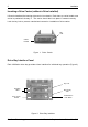
2 Installation Inserting a Drive Carrier (without a Drive Installed) Lift carrier handle while inserting drive carrier into chassis. Push down on carrier handle once carrier is pushed all the way in. The carrier should latch into place if inserted correctly. Lock the key lock to prevent unauthorized removal or installation of drive carrier.
Installation 3 Installing a Drive into the Drive Carrier NOTE: Before installing the drive into the carrier, the ID jumpers and spin-up option jumper on the disk drive must be removed. This is required so that the InfoStation itself can set the drive SCSI ID and spin-up option. 1. Install the drive(s) into the drive carrier(s). Drive(s) must be side-mounted into the drive carrier(s) using #6-32 Phillips Pan Hd. screws (Figure 3). 2.
4 Installation Inserting a Drive into the Chassis NOTES: A new drive can be inserted into an empty bay at anytime. However, the drive will not be ready for access until the following procedure is followed. The key lock is only to prevent unauthorized removal or installation of the drive carrier. Locking the key lock is not required for drive carrier operation. 1. Press and hold the Insert/Remove button (Figure 2) in until the Drive Ready LED starts to flash (approximately 3 seconds). 2.
Installation 5 Removing the Blower Module CAUTION: The blower module contains NO USER SERVICEABLE PARTS inside the unit. Warranty is VOID if module is opened. Refer ALL servicing to qualified service personnel! WARNING: DO NOT USE MODULE HANDLES TO LIFT CHASSIS! These handles are specifically designed for the installation and removal of modules only! NOTE : The blower module is hot-swappable. The chassis may remain on when removing and installing the blower module. 1.
6 Installation Removing the Power Supply Module CAUTION: The power supply module contains NO USER SERVICEABLE PARTS inside the unit. Warranty is VOID if module is opened. Refer ALL servicing to qualified service personnel! WARNING: DO NOT USE MODULE HANDLES TO LIFT CHASSIS! These handles are specifically designed for the installation and removal of modules only! NOTE: The power supply module is hot-swappable. The chassis may remain on when removing and installing the power supply module. 1.
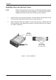
Installation 7 Installing the Power Cord Retainer Clip NOTE: Turn OFF power supply module and unplug power supply cord before installing retainer clip (included in the InfoStation accessory packet). 1. Turn OFF power to the power supply module via the power switch located on the module itself. If plugged in, unplug the power cord from the module. 2. Squeeze the retainer clip (Figure 6) and install onto the power supply module (as shown in Step 1 of Figure 7). 3.
8 Installation 2 1 Power Supply Module Retainer Clip AC Power Cord IFS14_24 Retainer Clip 3 Retainer Clip AC Power Cord Figure 7: Installing the Power Cord Retainer Clip NOTE: When removing the power supply module, check to make sure the retainer clip (if installed) is not blocking the power supply module handle (handle pivots outward). Damage to the retainer clip may occur otherwise. StorCase Technology, Inc. InfoStation 9-Bay Installation Guide - Rev.
Installation 9 Removing and Installing the I/O Module (Procedure and information below applies to both the I/O Module and I/O Repeater Module) CAUTION: Remove ALL power from the InfoStation before removing the I/O module. The I/O module contains NO USER SERVICEABLE PARTS inside the unit. Refer ALL servicing to qualified service personnel! VHDCI connectors are easily damaged by improper handling. Visually inspect each connector for bent contacts and carefully align prior to insertion.
10 Installation Removing the InfoStation Access Panel CAUTION: Remove ALL power from the InfoStation before removing the access panel(s). The InfoStation contains NO USER SERVICEABLE PARTS inside the unit. Warranty is VOID if any of the modules inside the InfoStation are opened. Refer ALL servicing to qualified service personnel! 1. Unplug the InfoStation and verify that ALL cables have been disconnected. 2. Place the InfoStation on a soft clean surface to protect finish of the chassis. 3.
Installation 11 Figure 10 below shows the inside of the InfoStation chassis (single-channel configuration) with the access panel removed. I/O Module Jumper Block Jumper Block Jumper Block Terminator Block IFS14_20 Figure 10: Single-Channel Backplane Configuration InfoStation 9-Bay Installation Guide - Rev. B00 StorCase Technology, Inc.
12 Installation Configuring the InfoStation for Dual-Channel CAUTION: Remove ALL power from the InfoStation before removing the I/O module. The I/O module contains NO USER SERVICEABLE PARTS inside the unit. Refer ALL servicing to qualified service personnel! NOTES: The InfoStation 9-bay supports daisy-chaining for Ultra160 applications only. Optional I/O interfaces are available as an upgrade. Contact StorCase for further ordering information. 1.
Installation 13 Module #2 (Channel 2) Module #1 (Channel 1) InfoStation Rear IFS14_33 Figure 12: Dual-Channel Rear Panel Configuration I/O Module Jumper Block Terminator Block I/O Module Jumper Block Terminator Block IFS14_21 Figure 13: Dual-Channel Backplane Configuration InfoStation 9-Bay Installation Guide - Rev. B00 StorCase Technology, Inc.
14 Installation Configuring the InfoStation for 4-Channel CAUTION: Remove ALL power from the InfoStation before removing the I/O module. The I/O module contains NO USER SERVICEABLE PARTS inside the unit. Refer ALL servicing to qualified service personnel! NOTES: The InfoStation 9-bay supports daisy-chaining for Ultra160 applications only. Optional I/O interfaces are available as an upgrade. Contact StorCase for further ordering information. 1.
Installation 15 Dual RAID Controller Module Unit Installation CAUTION: Remove ALL power from the InfoStation before installing the Dual RAID Controller Module unit. The RAID Controller Module contains NO USER SERVICEABLE PARTS inside. Warranty is VOID if module is opened.
16 Installation Module Option Cover Plate Phillips F.H. Screw (4 Total) IFS9_2 Figure 15: Removing the Module Option Cover Plate Installing the Dual RAID Controller Module Unit 1. Carefully slide the Dual RAID Controller Module Unit into the chassis and tighten the two (2) captive screws (Figure 16). Captive Screw (2 Total) Dual RAID Controller Module Unit InfoStation Chassis IFS9_11 Figure 16: Installing the Dual RAID Controller Module Unit StorCase Technology, Inc.
Installation 17 Installing/Removing a Single RAID Controller Module NOTE: Cover plate (provided) must be installed if a module slot is left empty. Installation of the cover plate is necessary for proper cooling inside chassis. 1. To remove a Single RAID Controller Module, loosen the Locking Thumbscrew and pull on handle to slide out the Single RAID Controller Module (Figure 17). 2. To install a Single RAID Controller Module, simply reverse above mentioned steps.
18 Installation Installing the RAID Battery Backup Unit(s) into the InfoStation CAUTION: Remove ALL power from the InfoStation before installing the RAID Battery Module(s). The RAID Controller Module unit contains NO USER SERVICEABLE PARTS inside. Warranty is VOID if module is opened. Refer ALL servicing to qualified service personnel! Danger of explosion if the RAID battery is incorrectly replaced! Replace only with the same or equivalent type recommended by the manufacturer.
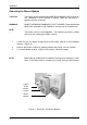
Installation 19 Blank Plate #6-32 Phillips F.H. Screw Blower module IFSII_DR8 Figure 19: Installation Location of RAID Battery Backup Unit Blower Module RAID Battery Backup Unit Thumbscrew IFSII_DR9 Figure 20: Installing the RAID Battery Backup Unit into the Blower Module InfoStation 9-Bay Installation Guide - Rev. B00 StorCase Technology, Inc.
20 Installation If installing only one (1) RAID Battery Backup Unit (for use with the Single RAID Controller Module unit), the Battery Backup Unit must be installed into the correct blower module. Refer to Figure 21 for correct Battery Backup Unit installation locations.