StorCase® Technology InfoStation® 9-Bay SCSI Ultra320 External Expansion Chassis User's Guide
i StorCase® Technology InfoStation® 9-Bay SCSI Ultra320 External Expansion Chassis User's Guide Part No. D89-0000-0163 C02 September 2003 StorCase Technology, Inc. 17600 Newhope Street Fountain Valley, CA 92708-9885 Phone (714) 438-1850 Fax (714) 438-1847 InfoStation 9-Bay User's Guide - Rev. C02 StorCase Technology, Inc.
ii LIMITED WARRANTY STORCASE TECHNOLOGY, Incorporated (StorCase) warrants that its products will be free from defects in material and workmanship, subject to the conditions and limitations set forth below. StorCase will, at its option, either repair or replace any part of its product that proves defective by reason of improper workmanship or materials.
iii Free Technical Support StorCase provides free technical support. If you experience any difficulty during the installation or subsequent use of a StorCase product, please contact StorCases Technical Support Department prior to servicing your system. This warranty covers only repair or replacement of defective StorCase products, as described above. StorCase is not liable for, and does not cover under warranty, any costs associated with servicing and/or installation of StorCase products.
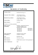
iv Declaration of Conformity Company Name: StorCase Technology, Inc.
v Federal Communications Commission (FCC) Statement RADIO FREQUENCY INTERFERENCE STATEMENT You are cautioned that changes or modifications not expressly approved by the party responsible for compliance could void your authority to operate that equipment. This device complies with part 15 of the FCC rules.
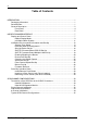
vi Table of Contents INTRODUCTION ..................................................................................................................... Packaging Information .................................................................................................. Serial Number ................................................................................................................ General Description ...........................................................................................
vii Table of Contents (cont'd) APPENDICES ........................................................................................................................ Appendix A - Specifications/Dimensions .................................................................. Appendix B - Optional Accessories ......................................................................... SCSI I/O Kits ........................................................................................................
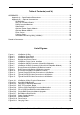
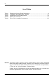
viii List of Tables Table 1: Table 2: Table 3: Table 4: Table 5: Display and Control Panel Components .............................................................. 8 InfoStation Menu Navigation Switches ............................................................. 11 Default Bay SCSI ID Assignments ..................................................................... 14 Motor Spin Functions .........................................................................................
Introduction 1 INTRODUCTION CAUTION: The InfoStation contains NO USER SERVICEABLE parts inside the unit. Refer ALL servicing to qualified service personnel! VHDCI connectors are easily damaged by improper handling. Visually inspect each connector for bent contacts and carefully align prior to insertion. NOTES: The InfoStation 9-bay supports daisy-chaining for Ultra160 applications only.
2 Introduction General Description The StorCase ® Technology InfoStation ® intelligent rack-mount expansion chassis is designed to support the latest high-density, high-speed SCSI disk drive technologies for use in network server, fault-tolerant and/or mission-critical applications. The InfoStation is designed to support 3.5" form factor, half-height (up to 1.6" high) SCSI Ultra320 devices. The InfoStation's dual backplane design can accommodate up to nine (9) single-connect SCA SCSI devices (Figure 1).
Introduction 3 Using a modular approach supported by redundant features and hot swapping capabilities, the InfoStation will provide continued data availability and allow for ease of maintenance and minimal system down time. The modular and scalable design of the InfoStation chassis also allows a variety of future product upgrades to be offered, such as future support for Fibre host interfaces.
4 Introduction Bay Identify LED(s) - Indicate that the drive bay is currently being selected for SCSI ID set-up (via the UI Module). Drive Bay LED(s) - Provides the following information: Drive Ready Indicates that the drive is properly installed and ready for access. Drive Activity - Indicates that the drive is being accessed. Drive Fault - Indicates a drive failure.
Introduction 5 Rear Panel (Figure 3) I/O Module(s) - InfoStation comes equipped with either one, two, or four Ultra320 I/O modules or Ultra160 I/O repeater modules (for daisy-chaining applications). Additional I/O interfaces are available, for up to four (4) channels. Refer to Appendix B for further information. NOTE: The InfoStation 9-bay supports daisy-chaining for Ultra160 applications only. I/O Module LED(s) Error LED (Amber) - Flashing indicates a detection in either: 1. Over temperature 2.
6 Introduction Power Supply Module(s) - Depending on the model, either one (1) or two (2) 450W redundant, hot swappable power supply modules. Each module features overvoltage and overcurrent protection, total usage hours, and power supply fault detection. Power Supply Module LED(s) Green LED - Steady glow indicates normal power supply operation. No glow indicates no A/C power or abnormal DC voltage range. Red LED - Flashing indicates temperature or over/undervoltage conditions.
InfoStation User Interface 7 INFOSTATION USER INTERFACE CAUTION: The User Interface Module contains NO USER SERVICEABLE PARTS inside the unit. Warranty is VOID if module is opened. Refer all servicing to qualified service personnel! The StorCase InfoStation is an intelligent external expansion chassis. Each InfoStation is equipped with a comprehensive User Interface (UI) which provides chassis status based on several internal environmental sensors.
8 InfoStation User Interface Table 1: NOTE: Display and Control Panel Components Alarm conditions cannot be reset! An alarm condition will automatically reset when the status of the failed component returns to normal. StorCase Technology, Inc. InfoStation 9-Bay User's Guide - Rev.
InfoStation User Interface 9 The UI Module (together with the drive bay, blower, power supply, and I/O modules) provides the following enclosure monitoring and control capabilities: 1. Average internal temperature and the ambient external temperature of the InfoStation chassis 2. InfoStation system 5V and 12V readings 3. SCSI mode for each channel 4. Type of RAID Controller Module installed 5. Buzzer enable/disable 6. Drive bay SCSI ID set-up 7. Drive bay spin-up options set-up 8.
10 InfoStation User Interface At the Factory-Default Display, the user can view the User-Selectable Default Displays (shown below) by simply using the UP and DOWN keys (refer to section "InfoStation Menu System" for further information). BANNER This display shows either the factory-default banner (StorCase), or a user-defined one. A user-defined banner can be up to 8-characters long.
InfoStation User Interface 11 InfoStation Menu System The menu system navigation is done using the Enter, Cancel, Up, and Down switches. The following table describes the specific function of each navigation button. Table 2: Switch InfoStation Menu Navigation Switches Description Enter This button is used to select an item at any level. If the Enter button is pushed at the last menu item, a detailed description of that particular menu item will be scrolled across the display.
12 InfoStation User Interface InfoStation Environmental Information and Set-Up Status The following steps show how to access the various InfoStation status information. NOTE: Press CANCEL at anytime to exit the menu system and return to the Default Display. The menu system will automatically cancel after 15 seconds of User inactivity. TEMP:xxC ENTER 1. Press ENTER at the Default Display so that display = Status. 2. Press ENTER so that display = Avg:xxC.
InfoStation User Interface 13 System Error Status The following steps show how to view InfoStation error conditions. NOTE: Press CANCEL at anytime to exit the menu system and return to the Default Display. 1. Press ENTER at the Default Display so that display = Status. 2. Press DOWN until display = Error. 3. Press ENTER and any errors present will be displayed. Press Up or Down to scroll through the error list. If no error is present, then display will read "No Error".
14 InfoStation User Interface Drive Bay SCSI ID Configuration Although the InfoStation will operate properly without the Display and Control Panel, no status will be reported, and the drive bay SCSI IDs must be configured as follows: - If a drive bay's SCSI ID has not been configured previously, the SCSI ID will default to the values listed in Table 3 below. - If a drive bay's SCSI ID has been configured previously, the configured SCSI ID will be assumed.
InfoStation User Interface 15 The following steps show how to set-up the drive bay SCSI ID via the Display and Control Panel. NOTE: NOTE: Press CANCEL at anytime to exit the menu system and return to the Default Display. The menu system will automatically cancel after 15 seconds of User inactivity. 1. Press ENTER at the Default Display so that display = Status. 2. Press DOWN until display = Bay Cfg. 3. Press ENTER so that display = SCSI ID. 4. Press ENTER again until display = BAY1:0.
16 InfoStation User Interface Spin-Up Option Set-Up The following steps show how to change the InfoStation drive bay spin-up option. NOTE: NOTE: Press CANCEL at anytime to exit the menu system and return to the Default Display. The menu system will automatically cancel after 15 seconds of User inactivity. 1. Press ENTER at the Default Display so that display = Status. 2. Press DOWN until display = Bay Cfg. 3. Press ENTER so that display = SCSI ID. 4. Press DOWN until display = Spin up. 5.
InfoStation User Interface 17 Table 4: Spin-Up Option Settings InfoStation 9-Bay User's Guide - Rev. C02 StorCase Technology, Inc.
18 InfoStation User Interface SAF-TE Processor Board SCSI ID Set-Up The following steps show how to change the SAF-TE processor board SCSI ID. NOTES: Only necessary if the optional SAF-TE processor board is installed. Factory default SAF-TE Processor Board SCSI ID is 15. Press CANCEL at anytime to exit the menu system and return to the Default Display.The menu system will automatically cancel after 15 seconds of User inactivity. NOTE: 1. Press ENTER at the Default Display so that display = Status. 2.
InfoStation User Interface 19 SAF-TE Processor Board Multiple LUN Set-Up The following steps show how to change the SAF-TE processor board Multiple LUN set-up. The Multiple LUN feature is only supported by the StorCase RAID Controller. Change the setting (to Single LUN) when using the optional SAF-TE board in conjunction with a non-StorCase RAID Controller (such as a PCI-based controller).
20 InfoStation User Interface Enabling/Disabling the Buzzer The following steps show how to enable/disable the InfoStation alarm/warning buzzer. NOTE: Press CANCEL at anytime to exit the menu system and return to the Default Display. The menu system will automatically cancel after 15 seconds of User inactivity. StorCase Technology, Inc. 1. Press ENTER at the Default Display so that display = Status. 2. Press DOWN until display = Buzzer. 3. Press ENTER so that display = BUZ=ON (or BUZ=OFF).
InfoStation User Interface 21 Enclosure ID Set-Up The following steps show how to view and change the InfoStation Enclosure ID. NOTE: Press CANCEL at anytime to exit the menu system and return to the Default Display. The menu system will automatically cancel after 15 seconds of User inactivity. TEMP:xxC ENTER 1. Press ENTER at the Default Display so that display = Status. 2. Press DOWN until display = Setup. 3. Press ENTER so that display = Enc. ID. 4. Press ENTER so that display = Enc. ID=x.
22 InfoStation User Interface Changing the Blower Speed The following steps show how to change the InfoStation blower speed. NOTE: Press CANCEL at anytime to exit the menu system and return to the Default Display. The menu system will automatically cancel after 15 seconds of User inactivity. TEMP:xxC ENTER 1. Press ENTER at the Default Display so that display = Status. 2. Press DOWN until display = Setup. 3. Press ENTER so that display = Enc. ID. 4. Press DOWN until display = FanSpeed. 5.
InfoStation User Interface 23 Serial Port Set-Up The following steps show how to view and change the InfoStation serial port option. NOTE: Press CANCEL at anytime to exit the menu system and return to the Default Display. The menu system will automatically cancel after 15 seconds of User inactivity. TEMP:xxC ENTER 1. Press ENTER at the Default Display so that display = Status. 2. Press DOWN until display = Setup. 3. Press ENTER so that display = Enc. ID. 4. Press DOWN until display = Ser.
24 InfoStation User Interface Serial Port Set-Up (cont'd) NOTES: Press CANCEL at anytime to exit the menu system and return to the Default Display. The menu system will automatically cancel after 15 seconds of User inactivity. Factory default Serial Port Set-Up is S.Port0. The following lists each InfoStation serial port option and its description. S.Port0 = InfoMon monitoring via the UI Module Serial Port (refer to the InfoMon User's Guide for further information). S.
InfoStation User Interface 25 Fiber Channel Speed Set-Up The following steps show how to change the InfoStation Fibre Channel Speed. NOTE: Press CANCEL at anytime to exit the menu system and return to the Default Display. The menu system will automatically cancel after 15 seconds of User inactivity. TEMP:xxC 1. Press ENTER at the Default Display so that display = Status. 2. Press DOWN until display = Setup. 3. Press ENTER so that display = Enc. ID. 4. Press DOWN until display = FC Speed. 5.
26 InfoStation User Interface Banner Set-Up The following steps show how to customize the InfoStation start-up banner. NOTE: Press CANCEL at anytime to exit the menu system and return to the Default Display. The menu system will automatically cancel after 15 seconds of User inactivity. TEMP:xxC ENTER 1. Press ENTER at the Default Display so that display = Status. 2. Press DOWN until display = Setup. 3. Press ENTER so that display = Enc. ID. 4. Press DOWN until display = Banner. 5.
InfoStation User Interface 27 Firmware Revision The following steps show how to access InfoStation firmware revision information. NOTE: Press CANCEL at anytime to exit the menu system and return to the Default Display. The menu system will automatically cancel after 15 seconds of User inactivity. TEMP:xxC ENTER 1. Press ENTER at the Default Display so that display = Status. 2. Press DOWN until display = Version. 3. Press ENTER to display the Firmware revision number.
28 InfoStation User Interface Drive Bay Interface Panel Each InfoStation drive bay provides a User interface for individual bay operation (Figure 5) Key Lock Drive Bay LEDs Bay Identify LED Insert/Remove Push Button Drive Carrier Handle IFS9_9 Figure 5: Drive Bay Interface Panel The Drive Bay Interface Panel consists of the following indicators and buttons: Table 5: Drive Ready LED Drive Bay Interface Components Steady glow indicates that drive is inserted and ready for access.
InfoStation User Interface 29 Insert/Remove Push Button NOTE: Refer to the InfoStation Installation Guide for detailed information on inserting/ removing drives from the InfoStation chassis. The operator must follow the procedures below to remove or insert a drive carrier (with drive installed) into the InfoStation drive bay. Inserting a Drive Carrier (with Drive Installed) NOTES: A new drive can be inserted into an empty bay at anytime.
30 SCSI Channel Configurations SCSI CHANNEL CONFIGURATIONS Termination of the SCSI Bus at the VHDCI Connectors Ultra320 I/O Module CAUTION: VHDCI connectors are easily damaged by improper handling. Visually inspect each connector for bent contacts and carefully align prior to insertion. NOTES: Port-A does not require a terminator (it is terminated internally). Port-A connects to SCSI Host.
SCSI Channel Configurations 31 Ultra160 I/O Repeater Module CAUTION: When using the double-stacked VHDCI connectors (Port A-1 & A-2) simultaneously, offset VHDCI cable connectors must be used for proper fit. Failure to use proper cables may result in damage to the I/O repeater module VHDCI connectors! VHDCI connectors are easily damaged by improper handling. Visually inspect each connector for bent contacts and carefully align prior to insertion.
32 SCSI Channel Configurations Single-Channel InfoStation NOTES: The InfoStation 9-bay supports daisy-chaining for Ultra160 applications only. Up to fifteen (15) drives maximum per SCSI channel. Optional I/O interfaces are available as an upgrade. Refer to Appendix B for further information. The InfoStation scalable backplane design allows either a single, dual, or four channel configuration. Figure 8 below shows the location of the I/O Module on the chassis rear panel for a singlechannel configuration.
SCSI Channel Configurations 33 Dual-Channel InfoStation NOTES: The InfoStation 9-bay supports daisy-chaining for Ultra160 applications only. Up to fifteen (15) drives maximum per SCSI channel. Optional I/O interfaces are available as an upgrade. Refer to Appendix B for further information. Figure 9 below shows the location of the I/O Modules on the chassis rear panel for a dualchannel configuration, and the corresponding drive-to-channel assignments.
34 SCSI Channel Configurations 4-Channel InfoStation NOTES: The InfoStation 9-bay supports daisy-chaining for Ultra160 applications only. Up to fifteen (15) drives maximum per SCSI channel. Optional I/O interfaces are available as an upgrade. Refer to Appendix B for further information. Figure 10 below shows the location of the I/O Modules on the chassis rear panel for a 4-channel configuration, and the corresponding drive-to-channel assignments.
SCSI Channel Configurations 35 Typical SCSI Channel Configurations CAUTION: VHDCI connectors are easily damaged by improper handling. Visually inspect each connector for bent contacts and carefully align prior to insertion. NOTES: The InfoStation 9-bay supports daisy-chaining for Ultra160 applications only. The installation, configuration, and use of the StorCase InfoStation chassis requires a certain level of expertise and experience on the part of the user/integrator.
36 SCSI Channel Configurations SCSI Host #2 SCSI Host #1 Terminate or Cascade to another InfoStation (Ultra160 applications only) I/O Repeater Module #1 IFS9_16 Figure 12: Typical Dual SCSI Host Connection to InfoStation (Single-Channel InfoStation with I/O Repeater Module) StorCase Technology, Inc. InfoStation 9-Bay User's Guide - Rev.
SCSI Channel Configurations NOTES: 37 InfoStation 9-Bay supports daisy-chaining for Ultra160 applications only. Maximum 15 Disks per SCSI Channel. T T I/O Repeater Module #2 I/O Repeater Module #1 Disk Ch. 2 (5 Disks) Disk Ch. 1 (4 Disks) InfoStation #2 To Host #2 I/O Repeater Module #2 I/O Repeater Module #1 Disk Ch. 2 (5 Disks) Disk Ch.
38 SCSI Channel Configurations This Page Left Blank Intentionally. StorCase Technology, Inc. InfoStation 9-Bay User's Guide - Rev.
Appendix A - Specifications/Dimensions 39 APPENDICES InfoStation 9-Bay User's Guide - Rev. C02 StorCase Technology, Inc.
40 Appendix A - Specifications/Dimensions Appendix A - Specifications/Dimensions The following InfoStation 9-bay specifications and dimensions are provided for reference only.
Appendix A - Specifications/Dimensions 41 StorCase InfoStation SCSI Ultra320 Rack Mount Enclosure 9 Bay # of BaySupported 9 # of Drive Carriers Included 9 Max. # of Drives Supported 9 Max. Storage Capacity 1.
42 Appendix A - Specifications/Dimensions StorCase InfoStation SCSI Ultra320 Rack Model Enclosure External Monitoring Utility via RS-232 Port Power-On-Hour (POH) Monitoring Yes Yes Audible Alarm Yes Standard 19 Rack-Mount Height = 4U Technical Support Toll-Free Warranty 7 Years Regulatory Approvals EMI Safety Agency StorCase Technology, Inc. FCC/CE/C-tick CSA/CSA US/TUV InfoStation 9-Bay User's Guide - Rev.
Appendix A - Specifications/Dimensions 43 16.92 (429.8mm) 20.57 (522.5mm) Front View Top View Right Side View 6.95 (176.5mm) 18.98 (482.1mm) 20.98 (532.89mm) IFS9_1 Figure A-1: InfoStation 9-Bay Physical Dimensions (Dimensions are for reference only) InfoStation 9-Bay User's Guide - Rev. C02 StorCase Technology, Inc.
44 Appendix B - Optional Accessories Appendix B - Optional Accessories SCSI I/O Kits Ultra320 I/O Module Kits The InfoStation's scalable backplane design allows additional I/O module and terminator kits to be offered, supporting a variety of Ultra320 drive-to-channel configurations. Additional I/O module kits (P/N S10A117) are available to upgrade the single and dual-channel models to a total of four (4) Ultra320 channels. Each I/O module kit comes with an I/O module and terminator (Figures B-1).
Appendix B - Optional Accessories 45 Ultra160 I/O Repeater Kits NOTE: The InfoStation 9-bay supports daisy-chaining for Ultra160 applications only. The InfoStation's scalable backplane design allows additional I/O repeater module and terminator kits to be offered, supporting a variety of Ultra160 drive-to-channel configurations. Additional I/O repeater module kits (P/N DXIFS-RPTR160-KIT) are available to upgrade the single and dual-channel models to a total of four (4) Ultra160 channels.
46 Appendix B - Optional Accessories SAF-TE Processor Board (Figure B-3) The SAF-TE Processor Board (P/N S10A100) is an optional upgrade for the InfoStation which is easily installed on the InfoStation's I/O Repeater Module. Features include: - Monitors status of each InfoStation blower, power supply module, and bay Monitors all nine (9) chassis temperature sensors Dedicated, user-selectable SCSI ID (via the InfoStation User Interface) Supports multi-mode (LVD/S.E.
Appendix B - Optional Accessories 47 RAID Controller Modules SCSI-to-SCSI RAID Controller Module The SCSI-to-SCSI RAID Controller Module units are internal RAID controllers specifically designed for the InfoStation chassis. The Single RAID Controller Module unit (P/N S10A122) is an Ultra160-to-Ultra160 stand-alone, dual host port controller with two SCSI disk channels (supporting 2x2 configurations).
48 Appendix B - Optional Accessories FC-to-SCSI RAID Controller Module The Fibre Channel-to-SCSI RAID Controller Module units are internal RAID controllers specifically designed for the InfoStation chassis. The Single RAID Controller Module unit (P/N S10C103) is an FC-to-SCSI (Ultra160) stand-alone, dual host port controller with four (4) SCSI disk channels (supporting 2x4 configurations).
Appendix B - Optional Accessories 49 IFS9_14 Figure B-6: Single RAID Controller Module Upgrade InfoStation 9-Bay User's Guide - Rev. C02 StorCase Technology, Inc.
50 Appendix B - Optional Accessories Slide Rail Kit The optional slide rail kit (P/N DXRCK-SLIDE) provides a convenient method to attach the InfoStation to a rack mount enclosure (Figure B-7). These high quality, durable rails provide 24 ball bearing rollers and have a quick-release button which allows quick and easy installation and removal of the InfoStation unit from its rack enclosure. Contact StorCase for further ordering information.
Appendix B - Optional Accessories 51 Optional Power Supply Module CAUTION: The power supply module contains NO USER SERVICEABLE PARTS inside the unit. Warranty is VOID if module is opened. Refer ALL servicing to qualified service personnel! NOTE: Refer to the InfoStation Installation Guide for further information. An optional second 450W power supply module (P/N S10A109) is available for the InfoStation chassis as shown in Figure B-8. Contact StorCase for further ordering information.
52 Appendix B - Optional Accessories Optional Blower Module CAUTION: The blower module contains NO USER SERVICEABLE PARTS inside the unit. Warranty is VOID if module is opened. Refer ALL servicing to qualified service personnel! NOTE: Refer to the InfoStation Installation Guide for further information. An optional second blower module (P/N S10A110) is available for the InfoStation chassis as shown in Figure B-9. Contact StorCase for further ordering information.
Appendix B - Optional Accessories 53 Carrying Case (Figure B-11) The optional molded plastic carrying case (P/N DX100-DE-C) is designed to transport the InfoStation drive carrier from one site to another in a safe, impact and moisture resistant environment. Its compact dimensions, 7" long x 9" wide x 4" high, make it easy to carry and store. The foam lining is contoured to fit a single InfoStation carrier. Contact your StorCase dealer for further details and ordering information.
54 Appendix B - Optional Accessories InfoStation Monitoring Utility (InfoMon®) The InfoStation InfoMon is a web-based monitoring utility that runs under the Windows O/S. This free utility (and its accompanying User's Guide) is available for download at the StorCase web site (http://www.storcase.com). The primary purpose of InfoMon is to continuously monitor the environmental status and indicate alarm conditions inside the InfoStation chassis via a serial connection to a PC.
Reader's Comments 55 Reader's Comments Please take a few moments when your computer system is up and running to send us your ideas and suggestions for improving our products and documentation.
Reader's Comments CUT ALONG THIS LINE FROM BOTTOM TO TOP OF PAGE 56 FOLD ALONG THIS LINE AND STAPLE SHUT NO POSTAGE NECESSARY IF MAILED IN THE UNITED STATES B U S I N E S S R E P LY M A I L FIRST CLASS MAIL PERMIT NO. 10686 SANTA ANA, CA POSTAGE WILL BE PAID BY ADDRESSEE TECHNOLOGY CORPORATION 17600 NEWHOPE STREET FOUNTAIN VALLEY CA 92708-9885 StorCase Technology, Inc. InfoStation 9-Bay User's Guide - Rev.