StorCase® Technology Data Express® DE100i-A Removable AT/IDE Drive Enclosure User's Guide
i StorCase® Technology Data Express® DE100i-A Removable AT/IDE Drive Enclosure User's Guide Part No. D89-0000-0000 F01 December 2002 StorCase Technology, Inc. 17600 Newhope Street Fountain Valley, CA 92708-9885 Phone (714) 438-1850 Fax (714) 438-1847 DE100i-A User's Guide - Rev. F01 StorCase Technology, Inc.
ii LIMITED WARRANTY STORCASE TECHNOLOGY, Incorporated (StorCase) warrants that its products will be free from defects in material and workmanship, subject to the conditions and limitations set forth below. StorCase will, at its option, either repair or replace any part of its product that proves defective by reason of improper workmanship or materials.
iii Free Technical Support StorCase provides free technical support. If you experience any difficulty during the installation or subsequent use of a StorCase product, please contact StorCases Technical Support Department prior to servicing your system. This warranty covers only repair or replacement of defective StorCase products, as described above. StorCase is not liable for, and does not cover under warranty, any costs associated with servicing and/or installation of StorCase products.
iv Declaration of Conformity Company Name: StorCase Technology, Inc.
v Table of Contents INTRODUCTION ..................................................................................................................... Packaging Information .................................................................................................. Serial Numbers .............................................................................................................. Package Contents ................................................................................................
vi List of Figures Figure 1: Figure 2: Figure 3: Figure 4: Figure 5: Figure 6: Figure 7: Figure 8: Figure 9: Figure 10: Figure 11: Package Contents .......................................................................................... 1 DE100i-A Receiving Frame and Carrier ........................................................ 3 Receiving Frame Front Panel ......................................................................... 4 Receiving Frame Unit ID Number and Activity Display .................
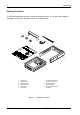
Introduction 1 INTRODUCTION Packaging Information The StorCase Technology Data Express® system is shipped in a container designed to provide protection and prevent damage during shipment. The Data Express unit was carefully inspected before and during the packing procedure at the factory. Bent or broken connectors, or evidence of other damage to the Data Express should be reported to the shipper immediately. Refer to Figure 1 for the package contents.
2 Introduction Package Contents The DE100i-A package contents include the following items. If any items are missing or damaged, contact your StorCase dealer for a replacement. 1 9 8 2 7 3 6 Da ta 4 Ex pre s s Disk (No Driv t Incl e ude d) Cab Cov (Pro er le vide d) Pow er I/O Cab Cable ID le Sele ct Cab Driv le e Car rier Driv Har e Phil 3/16 lipsdwareMountin Flat # 6-32(4ea g HD x ) 0151 Cab Scre le # Flat 6-32 ws (2Cover HD x 3/16plcs ) 0430A1 5 1. 2. 3. 4. 5. 6.
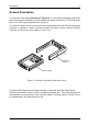
Introduction 3 General Description The StorCase Technology Data Express® DE100i-A is a removable lightweight drive carrier and receiving frame designed to provide durable and reliable mounting for 3.5 AT/IDE drives within 5.25" half-height peripheral slots (Figure 2). The DE100i-A allows a drive to be removed and transported to another DE100i-A-equipped computer or expansion chassis, and also provides the ability to secure sensitive data by removing and storing the drive safely for future use.
4 Introduction Receiving Frame Front Panel The Key Lock/Drive Power Switch performs three functions. The key lock assures proper seating of the drive carrier within the receiving frame, turns power to the drive carrier on and off, and prevents unauthorized removal or installation of the carrier. For the computer to access data on the DE100i-A disk drive, the key must be turned counterclockwise to the locked position.
Introduction 5 Receiving Frame Rear Panel DC Power Connector (J3): The DE100i-A uses a standard 4-pin DC Power Connector to accept DC power. I/O Connector (J2): The input/output connector provides a standard interface for all IDE signals. See Table 4 for J2 pin assignments. Activity Select Jumper (JP39): Default setting is "A" to use the activity indicator light on the Receiving Frame. Set to "B" to use the drive activity light on the computer chassis.
6 Installation INSTALLATION Installing the Drive into the Carrier While performing the steps in this section, work on a soft surface to prevent excessive shock to the drive being installed. Also refer to the manufacturer's documentation provided with the drive. NOTE: A #2 Phillips screwdriver will be required during this procedure. 1. Remove the drive from its protective packaging. 2.
Installation 7 and drive activity indicator light. A 3-pin wire-wrap connector is provided to enable you to fabricate a cable (cable not included) from the AT/IDE drive to the DE100i-A carrier circuit board. Figure 6 illustrates the Drive Carrier Circuit Board. Figure 6: DE100i-A Drive Carrier Circuit Board The J3 connector has three (3) pins: J3 Pin 1 should be connected to the Master signal of the disk drive. This signal indicates that this is the Master C: drive.
8 Installation Table 1 shows the signal levels on J3 Pin 1 & Pin 2 for different W1, W2, and W3 jumper settings. Connections to J3 Pin 1 should be made with signals from the drive that refer to Master, while connections to J3 Pin 2 should be made with signals from the drive that refer to Slave. Table 1: J3 Master/Slave Signal Levels * corresponds to a jumper installed on the carrier L (Low) corresponds to an installed jumper on the drive H (High) corresponds to a removed jumper on the drive.
Installation 9 If a slave drive is removed, Table 2 shows the signal levels on J3 Pin 1 & Pin 2 that will result for different W1, W2, and W3 jumper settings. Table 2: J3 Master (No Slave) Signal Levels * corresponds to a jumper installed on the carrier L (Low) corresponds to an installed jumper on the drive H (High) corresponds to a removed jumper on the drive. DE100i-A User's Guide - Rev. F01 StorCase Technology, Inc.
10 Installation J4, Pin 1 Power Connector J2, Pin 1 AT/IDE Interface J3 Pin 1 Required Jumper Wire 3-PIN WIRE WRAP CONNECTOR (Provided). Used for fabricating a single wire connection (wire not provided) between the drive and J3 Pin-1 on the drive carrier circuit board. E3 C/D J3 Pin1 SS D SP E1 E2 116 Drive Carrier Figure 7: Typical AT/IDE Drive Connections Typical AT/IDE drive jumper positions are shown in Figure 7. Remove and save all the jumpers.
Installation 11 Installation 1. Attach the I/O cable on the drive carrier circuit board to the drive. Refer to Figure 8 for an illustration of the installation process. 2. Attach the 4-pin power cable on the drive carrier circuit board to the drive. If you are installing only one drive carrier, skip to Step 4. Figure 8: Drive Installation Assembly 3.
12 Installation Installing the Receiving Frame The drive should be installed into the carrier before installing the receiving frame into the mounting bay of a computer or expansion chassis. NOTE: Use a #2 Phillips screwdriver during this procedure. 1. Turn OFF power to the computer. 2. Open the computer system according to the manufacturers instructions. If necessary, temporarily remove any expansion boards that may make installation difficult. 3.
Installation 13 Front of Unit Mounting Holes (Left) Mounting Holes (Right) Mounting Holes (Bottom) 0086 Figure 10: Receiving Frame Mounting Holes 6. To connect the drive to a Remote Activity LED in the computer system connect the appropriate cable(s) to the receiving frame rear panel as shown in Figure 5. Connect J7 Pins "A" & "C" to a remote activity LED. 7. Connect the I/O cable from the host adapter to the receiving frame. The Pin 1 indicator on the cable must be properly aligned.
14 Installation Selecting the Unit ID Number 1. Verify that power is turned on to the DE100i-A receiving frame by turning on your computer. You should see a number appear in the unit ID display window if the carrier is locked in place. 2. Unlock the drive carrier and remove it from the receiving frame. A "u" will be displayed initially when the unit is unlocked but will return to a number when the carrier is removed from the receiving frame.
Installation 15 Unit ID Number Display Unit ID Select Rotating Switch Lock and DC Power Switch Front of Unit Drive Carrier Guide Receiving Frame 0087 Drive Carrier (removed) Figure 11: Unit ID Select Switch Location Unit ID Select Switch Settings The following table lists the Unit ID Select Switch settings and the valid AT/IDE unit numbers. Please note that all invalid switch settings have shaded boxes and result in a blank display in the receiving frame display window.
16 Installation AT/IDE Interface Connector J2 The AT/IDE Interface connector (J2) pin assignments are as follows: Table 4: AT/IDE Interface Signals Pin 01 03 05 07 09 11 13 15 17 19 21 23 25 27 29 31 33 35 37 39 Signal Host ResetHost Data 7 Host Data 6 Host Data 5 Host Data 4 Host Data 3 Host Data 2 Host Data 1 Host Data 0 Ground Reserved HIOWHIORReserved Reserved IRQ 14 Host ADDR 1 Host ADDR 0 Host CS0DASP- I/O O I/O I/O I/O I/O I/O I/O I/O I/O O O I O O O Notes Pin 02 04 06 08 10 12 14 16 18 20 22 2
Appendix A - Specifications/Dimensions 17 APPENDICES DE100i-A User's Guide - Rev. F01 StorCase Technology, Inc.
18 Appendix A - Specifications/Dimensions Appendix A - Specifications/Dimensions Environmental Specifications Ambient Temperature Operating Storage -5° C to 50° C -45° C to 75° C Relative Humidity (1) 10% to 80% 10% to 90% Altitude -1000 to 50,000 ft -1000 to 50,000 ft -304m to 15240m -304m to 15240m 10g 60g Shock (1) (2) (2) Non-condensing with maximum gradient of 10% per hour. 11 msec pulse width 1/2 sine wave. Physical Specifications Carrier Receiving Frame Height 1.68" (42.
Appendix A - Specifications/Dimensions 19 Figure A-1: DE100i-A Physical Dimensions (Dimensions are for reference only) DE100i-A User's Guide - Rev. F01 StorCase Technology, Inc.
20 Appendix B - Attaching the ON/OFF Key Appendix B - Attaching the ON/OFF Key The following information describes the necessary steps to attach the ON/OFF key to the key lock mechanism so that it is non-removable, preventing accidental key loss. The procedure may be reversed at a later date to revert back to a removable key. 1. Make certain power is OFF to the receiving frame. Locate the rectangular shaped key lock mechanism access hole on the inside of the receiving frame.
Appendix C - Optional Accessories 21 Appendix C - Optional Accessories Carrying Case Drive Carrier DX100-DE-C Carrying Case 0014 Figure C-1: Carrying Case The optional molded plastic carrying case (P/N DX100-DE-C), is designed to transport the DE100i-A carrier from one site to another in a safe, impact and moisture resistant environment. Its compact dimensions, 7 long x 9 wide x 3.5 high, make it easy to carry and to store. The foam lining is contoured to fit a single DE100i-A carrier.
22 Appendix C - Optional Accessories Drive Cover The full drive cover (P/N DX100-COV), is an attractive metal cover which can provide additional protection to the drive, preventing foreign material from coming in contact with the drive and cables. The full drive cover is similar to the cable cover provided with the DE100i-A, except the full drive cover protects the drive as well as the cables. It is easily installed with two (2) #6-32 Phillips Flat Hd. screws as shown in the illustration below.
Appendix C - Optional Accessories 23 Drive Plug 0429 Figure C-3: Drive Plug The drive plug (P/N DX100-PLUG), is designed to fill system or external enclosure bays that are occupied by receiving frames that have no carrier units installed. The purpose of the plug is to provide an attractive and functional method of directing proper air flow to the other installed devices in the system or external enclosure. DE100i-A User's Guide - Rev. F01 StorCase Technology, Inc.
24 Appendix C - Optional Accessories Solenoid Drive Lock The factory installed solenoid option prevents premature removal of the carrier and drive unit until the target drive has fully spun down. For disk drives, this period of time can range from 15-40 seconds, depending on the type of drive being used (e.g. Barracuda drives require up to 50 seconds). Refer to the drive manufacturer's documentation for specific drive information.
25 Reader's Comments Please take a few moments when your computer system is up and running to send us your ideas and suggestions for improving our products and documentation.
Reader's Comments CUT ALONG THIS LINE FROM BOTTOM TO TOP OF PAGE 26 FOLD ALONG THIS LINE AND STAPLE SHUT NO POSTAGE NECESSARY IF MAILED IN THE UNITED STATES B U S I N E S S R E P LY M A I L FIRST CLASS MAIL PERMIT NO. 10686 SANTA ANA, CA POSTAGE WILL BE PAID BY ADDRESSEE TECHNOLOGY CORPORATION 17600 NEWHOPE STREET FOUNTAIN VALLEY CA 92708-9885 StorCase Technology, Inc. DE100i-A User's Guide - Rev.