
Manual


DE100i-A User's Guide - Rev. F01 StorCase Technology, Inc.
Introduction 5
JP39
J3
J2
J7
J4
+5
+12
GND
Reserved
J7A
J4A
Master Drive Select (0)
(Factory Configuration)
J4A J4A
Slave Drive
Select (1)
DC Power
Connector
J6
= Pin 1
A
B
Anode Cathode
Pin A
Pin C
A
C
B
D
Remote Drive
Activity
Reserved
AB
0421
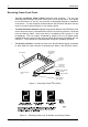
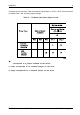
Figure 5: Receiving Frame Rear Panel
ReceivingFrameRearPanel
DC Power Connector (J3): The DE100i-A uses a standard 4-pin DC Power
Connector to accept DC power.
I/O Connector (J2): The input/output connector provides a standard interface for
all IDE signals. See Table 4 for J2 pin assignments.
Activity Select Jumper (JP39): Default setting is "A" to use the activity indicator
light on the Receiving Frame. Set to "B" to use the drive activity light on the computer
chassis. Refer to section "Configuring Connector J3" for more information.
Master/Slave Selection Jumper (J4A): Master Drive configuration (default).
Forces master drive configuration on receiving frame. Change jumper to set slave
drive configuration, or remove jumper to use Unit Select switch on receiving frame.
Master/Slave Connection (J6): Used for older model drives that do not support
a Slave Present handshake signal at I/O connector Pin-39. W hen using two receiving
frames a connection between J6 may be required.
Remote Drive Activity (J7): Pins "A" & "C" are used for remote drive activity. All
other pins are reserved.