StorCase Technology Data Express® DE100i-A66 Removable Ultra ATA/66 Drive Enclosure User's Guide
i StorCase Technology Data Express® DE100i-A66 Removable Ultra ATA/66 Drive Enclosure User's Guide Part No. D89-0000-0103 A00 June 2000 StorCase Technology Inc. 17600 Newhope Street Fountain Valley, CA 92708-9885 Phone (714) 438-1850 Fax (714) 438-1847 DE100i-A66 User's Guide - Rev. A00 StorCase Technology Inc.
ii LIMITED WARRANTY STORCASE TECHNOLOGY INC. ("StorCase") warrants that the following products will be free from defects in material and workmanship for a period of seven (7) years from the date of purchase from StorCase or its authorized reseller: all Data Silo® and Data Stacker® external expansion chassis, all Data Express® removable device enclosures and all StorCase interface cables and accessories specifically intended for use with these products.
iii Disclaimers The foregoing is the complete warranty for the products identified above and supersedes all other warranties and representations, whether oral or written. StorCase expressly disclaims all warranties for the identified products which are not stated herein, including, to the extent permitted by applicable law, any implied warranty of merchantability or fitness for a particular purpose.
iv Declaration of Conformity Company Name: StorCase Technology Inc. Corporate Office Address: 17600 Newhope Street Fountain Valley, CA 92708 Manufacturing Address: 3400 S.
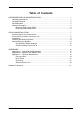
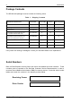
v Table of Contents DATA EXPRESS DE100i-A66 INTRODUCTION .................................................................... Packaging Information .................................................................................................. Package Contents ......................................................................................................... Serial Numbers ..............................................................................................................
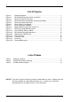
vi List of Figures Figure 1: Figure 2: Figure 3: Figure 4: Figure 5: Figure 6: Figure 7: Figure 8: Figure 9: Figure 10: Figure A-1: Figure B-1: Figure C-1: Figure C-2: Figure C-3: Figure C-4: Package Contents .......................................................................................... 1 DE100i-A66 Receiving Frame and Carrier .................................................... 3 Receiving Frame Front Panel .........................................................................
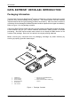
Introduction 1 DATA EXPRESS® DE100i-A66 INTRODUCTION Packaging Information The StorCase Technology Data Express® system is shipped in a container designed to provide protection and prevent damage during shipment. The Data Express unit was carefully inspected before and during the packing procedure at the factory. Bent or broken connectors, or evidence of other damage to the Data Express should be reported to the shipper immediately. Refer to Figure 1 for the package contents.
2 Introduction Package Contents The DE100i-A66 package contents include the following items: Table 1: Shipping Contents One StorCase Data Express ATA/66 Removable Enclosure Part Number DE100i-A66 (Carrier & RF) DE100i-CA66 DE100i-RA66 (Carrier) (Receiving Frame) Drive Carrier DE100i-CA66 (1) Receiving Frame DE100i-RA66 (1) (1) Alignment Tool D45-0000-0037 (1) (1) Phillips Mounting Screws (#6-32 x 3/16 F.H.
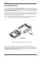
Introduction 3 General Description The StorCase Technology Data Express® DE100i-A66 is a removable drive carrier and receiving frame designed to provide durable and reliable mounting for 3.5 Ultra ATA/66 drives within 5.25" half-height peripheral slots (Figure 2). It is downward compatible with existing Ultra ATA/33, EIDE, and ATA drives.
4 Introduction Receiving Frame Front Panel The Key Lock/Drive Power Switch performs three (3) functions. The key lock assures proper seating of the drive carrier within the receiving frame, turns power to the drive carrier on and off, and prevents unauthorized removal or installation of the carrier. For the computer to access data on the DE100i-A66 drive, the key must be turned counterclockwise to the locked position.
Introduction 5 Figure 4: Receiving Frame Unit Number and Activity Display Receiving Frame Rear Panel DC Power Connector (J3): The DE100i-A66 uses a standard 4-pin DC Power Connector to accept DC power. I/O Connector (J2): The input/output connector provides a standard interface for all IDE signals. See Table 3 for J2 pin assignments. Master/Slave Selection Jumper (J5): Master Drive configuration (default). Forces master drive configuration on receiving frame.
6 Introduction Figure 5: Receiving Frame Rear Panel StorCase Technology Inc. DE100i-A66 User's Guide - Rev.
Installation 7 DE100i-A66 INSTALLATION Installing the Drive into the Carrier While performing the steps in this section, work on a soft surface to prevent excessive shock to the drive being installed. Also refer to the manufacturer's documentation provided with the drive. NOTE: A #2 Phillips screwdriver will be required during this procedure. 1. Remove the drive from its protective packaging. 2.
8 Installation Drive Activity Indicator Connector (J5) Jumper removed (factory default) disables drive activity indicator (Figure 4). Jumper installed enables drive activity indicator. NOTE: If two (2) drives are installed (with J5 enabled on both drives), both drive activity indicators will flash simultaneously, even if only one drive is being accessed. Installation 1. Attach the I/O cable on the drive carrier circuit board to the drive.
Installation 9 Installing the Receiving Frame The drive should be installed into the carrier before installing the receiving frame into the mounting bay of a computer or expansion chassis. NOTE: Use a #2 Phillips screwdriver during this procedure. 1. Turn OFF power to the computer. 2. Open the computer system according to the manufacturers instructions. If necessary, temporarily remove any expansion boards that may make installation difficult. 3.
10 Installation Front of Unit Mounting Holes (Left) Mounting Holes (Right) Mounting Holes (Bottom) 0086 Figure 9: Receiving Frame Mounting Holes 6. Connect the I/O cable from the host adapter to the receiving frame. The Pin 1 indicator on the cable must be properly aligned. Refer to Figure 5 for the correct Pin 1 location. 7. Connect the power cable from the DC power supply in the computer or expansion chassis to the power connector on the DE100i-A66 receiving frame.
Installation 11 WARNING: Unlocking the carrier unit switches DC power off to the drive. Since disk drives require a short amount of time to spin down, allow about 15 seconds before pulling the carrier unit out of the receiving frame to avoid possible damage to the drive. 3. Use the alignment tool supplied with the DE100i-A66 to select the ID number of the disk drive. Refer to Figure 10 for the location of the ID Select Switch inside the receiving frame.
12 Installation Unit ID Select Switch Settings The following table lists the Unit ID Select Switch settings and the valid AT/IDE unit numbers. Please note that all invalid switch settings have X's through them and result in a blank display in the receiving frame display window. Table 2: Unit ID Select Switch Settings NOTE: The unit ID number display is for ID display purposes only. The master/slave setting must be set on the drive itself. StorCase Technology Inc. DE100i-A66 User's Guide - Rev.
Installation 13 AT/IDE Interface Connector J2 The AT/IDE Interface connector (J2) pin assignments are as follows: Table 3: AT/IDE Interface Signals Pin 01 03 05 07 09 11 13 15 17 19 21 23 25 27 29 31 33 35 37 39 Signal Host ResetHost Data 7 Host Data 6 Host Data 5 Host Data 4 Host Data 3 Host Data 2 Host Data 1 Host Data 0 Ground DMARQ DIOWDIORReserved Reserved IRQ 14 Host ADDR 1 Host ADDR 0 Host CS0DASP- I/O O I/O I/O I/O I/O I/O I/O I/O I/O O O O I O O O Notes Pin 02 04 06 08 10 12 14 16 18 20 22 2
14 Appendix A - Specifications/Dimensions APPENDICES StorCase Technology Inc. DE100i-A66 User's Guide - Rev.
Appendix A - Specifications/Dimensions 15 Appendix A - Specifications/Dimensions Environmental Specifications Operating Storage Ambient Temperature -5° C to 50° C -45° C to 75° C Relative Humidity (1) 10% to 80% 10% to 90% Altitude -1000 to 50,000 ft -1000 to 50,000 ft -304m to 15240m -304m to 15240m 10g 60g Shock (2) Non-condensing with maximum gradient of 10% per hour. 11 msec pulse width 1/2 sine wave. (1) (2) Physical Specifications Carrier Height 1.68" (42.7mm) 1.70" (43.
16 Appendix A - Specifications/Dimensions Figure A-1: DE100i-A66 Physical Dimensions (Dimensions are for reference only) StorCase Technology Inc. DE100i-A66 User's Guide - Rev.
Appendix B - Attaching the ON/OFF Key 17 Appendix B - Attaching the ON/OFF Key The following information describes the necessary steps to attach the ON/OFF key to the key lock mechanism so that it is non-removable, preventing accidental key loss. The procedure can be reversed at a later date to revert back to a removable key. 1. Make certain power is OFF to the receiving frame. Access Hole Pawl Key/Lock Locate the rectangular shaped key lock mechanism access hole on the inside of the receiving frame.
18 Appendix C - Optional Accessories Appendix C - Optional Accessories Carrying Case Drive Carrier DX100-DE-C Carrying Case 0014 Figure C-1: Carrying Case The optional molded plastic carrying case (part number DX100-DE-C), is designed to transport the DE100i-A66 carrier from one site to another in a safe, impact and moisture resistant environment. Its compact dimensions, 7 long x 9 wide x 3.5 high, make it easy to carry and to store. The foam lining is contoured to fit a single DE100i-A66 carrier.
Appendix C - Optional Accessories 19 Drive Cover 1 Slip Drive Cover Lip into Top Rear of Carrier. The Sides of the Cover Will Fit Between the Drive and the Carrier. Mounting Holes Must be Towards Rear of Carrier. 1 3 Slide Drive Cover Forward Making Certain Front Cover Lip is Inside Carrier. Fasten Screws. 2 Drive Cover 3 2 Swing Drive Cover Down, Covering the Drive. Make Certain You Do Not Damage Connector Pins or Cables.
20 Appendix C - Optional Accessories Solenoid Drive Lock The factory installed solenoid option prevents premature removal of the carrier and drive unit until the target drive has fully spun down. For disk drives, this period of time can range from 15-40 seconds, depending on the type of drive being used (e.g. Barracuda drives require up to 50 seconds). Refer to the drive manufacturer's documentation for specific drive information.
21 Reader's Comments Please take a few moments when your computer system is up and running to send us your ideas and suggestions for improving our products and documentation.
Reader's Comments CUT ALONG THIS LINE FROM BOTTOM TO TOP OF PAGE 22 FOLD ALONG THIS LINE AND STAPLE SHUT NO POSTAGE NECESSARY IF MAILED IN THE UNITED STATES B U S I N E S S R E P LY M A I L FIRST CLASS MAIL PERMIT NO.