Kingston Technology DATA EXPRESS Removable SCSI Drive Enclosure With Wide Differential I/O User's Guide
i Kingston Technology's Data Express® DE100i-SWD Removable SCSI Drive Enclosure with 16-Bit Wide Differential I/O User's Guide Part No. D89-0000-0012 C00 December 1997 Kingston Technology Company 17600 Newhope Street Fountain Valley, CA 92708-9885 Phone (714) 438-1850 Fax (714) 438-1847 DE100i-SWD User's Guide - Rev.
ii Limited Warranty KINGSTON TECHNOLOGY COMPANY (“Kingston”) warrants that this product is free from defects in material and workmanship. Subject to the conditions and limitations set forth below, Kingston will, at its option, either repair or replace any part of this product which proves defective by reason of improper workmanship or materials. Repair parts or replacement products will be provided by Kingston on an exchange basis, and will be either new or refurbished to be functionally equivalent to new.
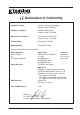
iii CE Declaration of Conformity Company’s Name: Kingston Technology Company Storage Products Division Company’s Address: 17600 Newhope Street Fountain Valley, CA 92708 Manufacturer’s Address: 11535 Martens River Circle Fountain Valley, CA 92708 Product Name: Data Express DE100i Model Number: DE100i-XSXX/XXX Conforms to the following specifications: Safety Agencies: CSA “Certified” UL TÜV “Bauart Geprüft” Safety Directive: Safety Tests: CAN/CSA-C22.2 No950-93 UL 1950 EN 60950/06.
iv Table of Contents DATA EXPRESS DE100i-SWD ............................................................................................... Packaging Materials ...................................................................................................... Package Contents ......................................................................................................... Serial Numbers .............................................................................................................
v List of Figures Figure Figure Figure Figure Figure Figure Figure Figure Figure Figure Figure Figure Figure Figure Figure Figure Figure Figure Figure Figure 1: 2: 3: 4: 5: 6: 7: 8: 9: 10: A-1: B-1: B-2: B-3: B-4: C-1: D-1: D-2: D-3: D-4: Data Express DE100i-SWD Package Contents ................................................ 1 DE100i-SWD Receiving Frame and Carrier ....................................................... 2 Receiving Frame Front Panel .....................................................
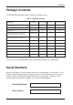
Introduction 1 Data Express® DE100i-SWD Packaging Materials The Kingston Technology Data Express® system is shipped in a container designed to provide protection and prevent damage during shipment. The Data Express unit was carefully inspected before and during the packing procedure at the factory. Bent or broken connectors, or evidence of other damage to the Data Express should be reported to the shipper immediately. Refer to Figure 1 for the package contents.
2 Introduction Package Contents The DE100i-SWD package contents include the following items: Table 1: Shipping Contents One Kingston Data Express SCSI System Part Number DE100i-SWD (Carrier & RF) DE100i-CSWD DE100i-RSWD (Carrier) (Receiving Frame) Drive Carrier DE100i-CSWD (1) Receiving Frame DE100i-RSWD (1) Alignment Tool D45-0000-0037 (1) Phillips Mounting Screws (6-32 by 3/16” F.H.
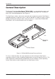
Introduction 3 General Description The Kingston Technology Data Express® DE100i-SWD is a removable drive carrier and receiving frame designed to provide durable and reliable mounting for 3.5” SCSI drives within 5.25" half-height peripheral slots (Figure 2). The Data Express allows a drive to be removed and transported to another Data Expressequipped computer or expansion chassis, and also provides the ability to secure sensitive data by removing and storing the drive safely for future use.
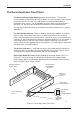
4 Introduction The Receiving Frame Front Panel • The Key Lock/Drive Power Switch performs three functions. The key lock assures proper seating of the drive carrier within the receiving frame, it turns power to the drive carrier "On" and "Off", and it prevents unauthorized removal or installation of the carrier. For the computer to access data on the Data Express disk drive, the key must be turned counter-clockwise to the locked position.
Introduction 5 Activity Indicator Carrier Removed from Receiving Frame Carrier Installed (unlocked) Carrier Installed (locked) The number "2" shown above is for illustration purposes only. It can be any valid unit ID number. However, the letter "u" (above middle), will appear as illustrated. 0064 Figure 4: Unit Number Display Conditions The Receiving Frame Rear Panel • I/O Connector (J2): The input/output connector provides a standard interface for all SCSI signals.
6 Installation DATA EXPRESS INSTALLATION Installing the Drive into the Carrier Preparation While performing the steps in this section, work on a soft surface to prevent excessive shock to the drive being installed. Also refer to the manufacturer's documentation provided with the drive. NOTE: A #2 Phillips screwdriver will be required during this procedure. 1. Remove the drive from its protective packaging. 2.
Installation 7 NOTE: SCSI units are provided with a single row 5-pin wire wrap connector. This connector allows fabrication of ID select cable connections for use in confined areas or for drives which have non-standard pin configurations. If required, install five wire wrap jumpers from the drive ID pins to the ID select connector located inside the carrier on the signal distribution board. See Figure 7 for the location of the ID Select Interface connector. Refer to page 8 for a typical drive connection.
8 Installation TYPICAL 2MM DRIVE ID PIN CONFIGURATION Figure 7 illustrates a typical SCSI ID select connection to a drive with 2mm ID select pins. The wires on the wire harness connect to the positive pin (or signal pins) on the disk drive. In some cases, the drive manufacturer will label the signal pins as Pin 1, 3, 5, 7, (instead of 0, 1, 2, 3 as shown in Figure 7 below). Also, in some cases, the even-numbered Pins 2, 4, 6 are used for Ground.
Installation 9 Installing the Receiving Frame The drive should be installed into the carrier before installing the receiving frame into the mounting bay of a computer or expansion chassis. NOTE: Use a #2 Phillips screwdriver during this procedure. 1. Turn off power to the computer. 2. Open the computer system according to the manufacturer’s instructions. If necessary, temporarily remove any expansion boards that may make installation difficult. 3.
10 Installation IMPORTANT NOTE: In order to use remote ID selection from a computer or expansion chassis, the Unit ID number on the Data Express receiving frame must be set to '0' with the provided alignment tool. Refer to the section "Selecting the Unit Number" later in this section for the Unit ID selection procedure. 4. With the drive carrier locked in place inside the receiving frame, install the Data Express into the 5.25” drive opening in the computer or expansion chassis.
Installation 11 8. Connect the power cable from the DC power supply in the computer or expansion chassis to the power connector on the Data Express receiving frame. Refer to Figure 5 for the Data Express receiving frame power connector location. 9. Replace any expansion boards that may have been removed earlier. Replace the system cover according to the manufacturer’s instructions. 10. Reconnect any system or peripheral cables removed earlier. 11. Turn on power to the computer.
12 Installation NOTE: 5. The lock on the Data Express receiving frame serves two functions: 1) as a lock to secure the drive; and 2) as a DC power switch for the carrier unit. The lock must be engaged (turned counterclockwise) in order to supply power to the drive carrier. The new drive may need to be formatted or initialized prior to use with the operating system and applications software, Refer to the drive and/or computer manufacturer's documentation for formatting information.
Installation 13 SCSI Interface Connector J2 The SCSI interface connector (J2) pin assignments are supplied for your convenience.
14 Kingston Technology Company Installation DE100i-SWD User's Guide - Rev.
Appendix A - Specifications/Dimensions 15 Appendices DE100i-SWD User's Guide - Rev.
16 Appendix A - Specifications/Dimensions Appendix A - Specifications/Dimensions SCSI Data Express subsystems conform to the Small Computer Systems Interface (SCSI) Standard set by the American National Standards Institute (ANSI).
Appendix A - Specifications/Dimensions Receiving Frame with Carrier .50 (12.7) 2.060 (52.3) 17 3.125 (79.4) .375 (9.5) 1.70 (43.2) 5.875 (149.2) #6-32 x 8 With Hot Swap Board DE100 Board 8.19 (208.0) Hot Swap Board 5.50 (139.7) .250 (6.4) 3.125 (79.4) .15 (3.8) #6-32 x 4 Bottom .64 (16.3) Carrier Only 1.68 (42.7) 7.38 (187.5) 4.665 (118.5) 3.75 (95.3) 1.75 (44.5) .245 (6.2) 0285A Figure A-1: Data Express Physical Dimensions DE100i-SWD User's Guide - Rev.
18 Appendix B - Factory-Installed Options Appendix B - Factory-Installed Options Hot Swap Feature The DE100 SCSI Hot Swap Board allows the installation, removal or exchange of Data Express carriers while your computer system is operating by monitoring and protecting the computer system and other peripheral devices on the SCSI Bus. The Hot Swap option eliminates the need to shut down your system when adding or removing a SCSI device by performing two functions: 1.
Appendix B - Factory-Installed Options 19 Receiving I/O Interface Frame Mother Connector Board Remove Mounting Screws and use to Fasten Hot Swap Board (2 plcs) 0639 Hot Swap Board Stand Offs (2 plcs) (Replace Mother Board Mounting Screws) SCSI Receiving Frame (Carrier Installed) Figure B-1: Attaching the Hot Swap Board Carrier Removal Follow the procedures below to remove the Data Express carrier from the receiving frame equipped with the Hot Swap option. 1. Verify that the drive is not active.
20 NOTE: Appendix B - Factory-Installed Options The timer for device spin down is controlled by a small selector, located in a cutout on the side of the Data Express Receiving Frame as shown in Figure B-2. When the key is turned to the off position, and when the timer receives a No SCSI Activity signal from the Hot Swap Board, it waits the specified delay time before displaying a “u” on the front panel of the Receiving Frame.
Appendix B - Factory-Installed Options 21 Jumper Options Jumper location W1 provides remote ID selection (Figure B-3). Jumper JP7, if installed, provides additional data protection during device spin-down. If the Data Express is switched off while the device is active, this jumper will prevent the device from spinning-down by monitoring the activity signal. When activity stops, the device will spin down normally.
22 Appendix B - Factory-Installed Options Solenoid Drive Lock The factory installed solenoid option prevents premature removal of the carrier and drive unit until the target drive has fully spun down. For most disk drives, this period of time can range from 15-40 seconds, depending on the type of drive being used (e.g. Seagate Barracuda drives require up to 50 seconds). Refer to the drive manufacturer's documentation for specific drive information.
Appendix C - Attaching the On/Off Key 23 Appendix C - Attaching the On/Off Key to Non-Solenoid Units The following information will provide the necessary steps to attatch the On/Off key to the key/lock mechanism so that it is non-removable, preventing accidental key loss. The procedure can be reversed if, at a later date, you want to remove the key. 1. Make certain power is off to the receiving frame.
24 Appendix D - Optional Accessories Appendix D - Optional Accessories Carrying Case Drive Carrier DX100-DE-C Carrying Case 0014 Figure D-1: Optional Data Express Carrying Case (DX100-DE-C) The optional molded plastic carrying case is designed to transport your Data Express carrier from one site to another in a safe, impact and moisture resistant environment. Its compact dimensions, 7” long x 9” wide x 3.5” high, make it easy to carry and to store.
Appendix D - Optional Accessories 25 Drive Cover 1 Slip Drive Cover Lip into Top Rear of Carrier. The Sides of the Cover Will Fit Between the Drive and the Carrier. Mounting Holes Must be Towards Rear of Carrier. 1 3 Slide Drive Cover Forward Making Certain Front Cover Lip is Inside Carrier. Fasten Screws. 2 Drive Cover 3 2 Swing Drive Cover Down, Covering the Drive. Make Certain You Do Not Damage Connector Pins or Cables.
26 Appendix D - Optional Accessories Write Protect Switch E IT R F W F O P R T C E T N O O Disk Drive Write Protect Switch Bracket and Cable Cover E IT R F W F O Disk Carrier T C E T N O O R P Write Protect Connector (attach to appropriate disk drive pins) (Disk Drive not shown for clarity) 0357A Figure D-3: Write Protect Switch The Data Express write protect switch (DX100-DEWP), easily mounts inside the device carrier of a Data Express unit.
Appendix D - Optional Accessories 27 Drive Plug 0429 Figure D-4: Drive Plug The Data Express Drive Plug (DX100-PLUG), is designed to fill system or external enclosure bays that are occupied by receiving frames that have no carrier units installed. The purpose of the plug is to provide an attractive and functional method of directing proper air flow to the other installed devices in the system or external enclosure. DE100i-SWD User's Guide - Rev.