
Manual


DE100i-SWD User's Guide - Rev. C00 Kingston Technology Company
Installation 9
Installing the Receiving Frame
The drive should be installed into the carrier before installing the receiving frame into the
mounting bay of a computer or expansion chassis.
NOTE: Use a #2 Phillips screwdriver during this procedure.
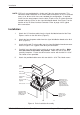
1. Turn off power to the computer.
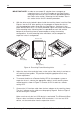
2. Open the computer system according to the manufacturer’s instructions. If
necessary, temporarily remove any expansion boards that may make installation
difficult.
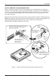
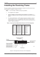
3. To select the Data Express unit ID remotely through the computer system or
external expansion chassis, the appropriate cable from the system must be
connected to the ID select connector (J4) on the rear of the receiving frame as
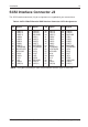
shown in Table 2 and Figure 8.
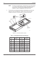
Table 2 - Receiving Frame Motherboard Connector J4 Pin Configuration
Pin 1 RESERVED Pin 11 RESERVED
Pin 2 RESERVED Pin 12 RESERVED
Pin 3 RESERVED Pin 13 Ground
Pin 4 RESERVED Pin 14 ID3
Pin 5 RESERVED Pin 15 Ground
Pin 6 RESERVED Pin 16 ID2
Pin 7 RESERVED Pin 17 Ground
Pin 8 RESERVED Pin 18 ID1
Pin 9 RESERVED Pin 19 Ground
Pin 10 RESERVED Pin 20 ID0
Figure 8: Receiving Frame Connector J4 Pin Configuration
0427B
Receiving Frame
Motherboard
Connector J4
Jumpers Installed
at Factory
Reserved
19
20
111
212
From System ID0
From System ID1
From System ID2
Ground
From System ID3