
Manual


Introduction 5
PATA DE110 User's Guide - Rev. C03 StorCase Technology, Inc.
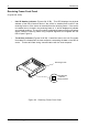
Figure 3B: Receiving Frame Unit ID Number and Activity Display
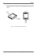
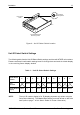
Drive Carrier
(Figure 4)
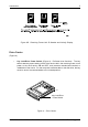
Key Lock/Drive Power Switch (Figure 4) - Performs three functions. The key
switch assures proper seating of the drive carrier within the receiving frame, turns
power to the drive carrier ON and OFF, and prevents unauthorized removal or
installation of the carrier. For the computer to access data on the disk drive, the key
must be turned counterclockwise to the locked position.
Key Lock/Drive
Power Switch
0841
Figure 4: Drive Carrier