StorCase® Technology Data Express® Ultra320 DE110 Removable SCSI Wide Ultra320 Drive Enclosure User's Guide
i StorCase® Technology Data Express® Ultra320 DE110 Removable SCSI Wide Ultra320 Drive Enclosure User's Guide Part No. D89-0000-0245 A03 August 2006 StorCase Technology, Inc. 17600 Newhope Street Fountain Valley, CA 92708-9885 Phone (714) 438-1850 Fax (714) 438-1847 Ultra320 DE110 User's Guide - Rev. A03 StorCase Technology, Inc.
ii LIMITED WARRANTY STORCASE TECHNOLOGY, Incorporated (“StorCase”) warrants that its products will be free from defects in material and workmanship, subject to the conditions and limitations set forth below. StorCase will, at its option, either repair or replace any part of its product that proves defective by reason of improper workmanship or materials.
iii Warranty Claim Requirements To obtain warranty service, the defective product must be returned to your local authorized StorCase dealer or distributor, or, with prior StorCase approval, to the StorCase factory service center. For defective products returned directly to StorCase, a Return Material Authorization (“RMA”) number must be obtained by calling StorCase Customer Service at (714) 445-3455. The RMA number must be prominently displayed on the outside of the return package.
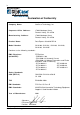
iv Declaration of Conformity Company Name: StorCase Technology, Inc.
v Table of Contents INTRODUCTION ........................................................................................................................ Packaging Information ................................................................................................... Serial Numbers ............................................................................................................... Package Contents ..........................................................................................
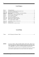
vi List of Figures Figure 1: Figure 2: Figure 3A: Figure 3B: Figure 4: Figure 5: Figure 6: Figure 7: Figure 8A: Figure 8B: Figure 9: Package Contents .............................................................................................. 2 Ultra320 DE110 Receiving Frame and Carrier .................................................. 3 Receiving Frame Front Panel ............................................................................. 4 Receiving Frame Unit ID Number and Activity Display ......
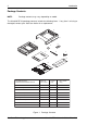
Introduction 1 INTRODUCTION Packaging Information The StorCase Technology Data Express® system is shipped in a container designed to provide protection and prevent damage during shipment. The Data Express unit was carefully inspected before and during the packing procedure at the factory. Bent or broken connectors, or evidence of other damage to the Data Express should be reported to the shipper immediately. Refer to Figure 1 for the package contents.
2 Introduction Package Contents NOTE: Package contents may vary, depending on model. The Ultra320 DE110 package contents include the following items. If any item is missing or damaged, contact your StorCase dealer for a replacement.
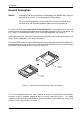
Introduction 3 General Description NOTES: Ultra320 DE110 receiving frames are indicated by their AMBER LED, while the Ultra320 DE110 carriers are indicated by the Ultra320 logo. For SCSI Ultra320 operation, the Ultra320 DE110 requires Ultra320 drives, Ultra320 HBA, and Ultra320-compliant cabling (internal and external).
4 Introduction Receiving Frame Front Panel (Figures 3A & 3B) • Unit ID Number Indicator - This AMBER LED displays the status of the Ultra320 DE110 device carrier if the carrier is Installed and Locked in the receiving frame or if the carrier is removed from the receiving frame. If the carrier is Installed but not Locked in the receiving frame, a "u" will be displayed to indicate an unlocked condition.
Introduction 5 Carrier Removed from Receiving Frame Carrier Installed (unlocked) Activity Indicator Carrier Installed (locked) 0064c Fan Failure The number "2" shown above is for illustration purposes only. It can be any valid unit ID number. The letter "u" and F will appear as illustrated. Figure 3B: Receiving Frame Unit ID Number and Activity Display Drive Carrier (Figure 4) • Key Lock/Drive Power Switch - Performs three functions.
6 Introduction Receiving Frame Rear Panel (Figure 5) • I/O Connector (J3) - The input/output connector provides a standard interface for all Ultra320 signals (Figure 5). • DC Power Connector (P1) - A standard 4-pin DC power connector is used to accept DC power. • Option Pin Connector (W1) Remote Unit ID Selection: Pins 1-8 of this connector are provided for remote unit SCSI ID selection through the computer system.
Installation 7 INSTALLATION NOTES: Ultra320 DE110 receiving frames are indicated by their AMBER LED, while the Ultra320 DE110 carriers are indicated by the Ultra320 logo. For SCSI Ultra320 operation, the Ultra320 DE110 requires Ultra320 drives, Ultra320 HBA, and Ultra320-compliant cabling (internal and external). Preparation NOTE: A #2 Phillips screwdriver will be required during this procedure.
8 Installation Ultra320 Drive (Not Included) Drive Carrier Board Drive Carrier 0835C #6-32 Phillips Flat Hd. Screw (4 each) Figure 6: Drive Installation Assembly StorCase Technology, Inc. Ultra320 DE110 User's Guide - Rev.
Installation 9 1 Insert this end into the carrier first 2 Slide the cover towards the back of the carrier 0836A 3 Secure with #6-32 Phillips Flat Hd. screws (2 Total) Figure 7: Drive Cover Installation Ultra320 DE110 User's Guide - Rev. A03 StorCase Technology, Inc.
10 Installation Installing the Receiving Frame NOTE: Use a #2 Phillips screwdriver for this procedure. The drive should be installed into the carrier before installing the receiving frame into the mounting bay of a computer or expansion chassis. 1. Turn OFF power to the computer. 2. Open the computer system according to the manufacturer’s instructions. If necessary, temporarily remove any expansion boards that may make installation difficult. 3.
Installation 11 Spacer Plates (Optional) NOTE: Depending on the computer system, spacer plates may be positioned on the receiving frame to utilize either top or bottom row of side-mounting holes (Figure 8B). The Ultra320 DE110 is designed to fit most computer systems with standard 5.25" peripheral slots. The installation of the spacer plates (provided) may or may not be necessary. Spacer Plate (2 Total) OR 0869 Figure 8B: Spacer Plate Installation (Optional) 5.
12 Installation 8. Reconnect any system or peripheral cables removed earlier. 9. Turn ON power to the computer. If the installation has been successful, and all the cables have been properly attached, the system should boot normally. Although the computer may not recognize the Ultra320 DE110 yet, the front panel display on the Ultra320 DE110 receiving frame should illuminate. 10. The new drive may need to be formatted or initialized prior to use with the operating system and applications software.
Installation 13 Unit ID Select Rotating Switch Drive Carrier Guide 0087a Typical Data Express Receiving Frame Figure 9: Unit ID Select Switch Location Table 1: Unit ID Display Hex Reference Table DISPLAY (HEX) UNIT NUMBER (10) 0 DISPLAY (HEX) UNIT NUMBER (10) 8 1 9 2 10 3 11 4 12 5 13 6 14 7 15 0147 Ultra320 DE110 User's Guide - Rev. A03 StorCase Technology, Inc.
14 Installation This Page Left Blank Intentionally. StorCase Technology, Inc. Ultra320 DE110 User's Guide - Rev.
Appendix A - Specifications/Dimensions 15 APPENDICES Ultra320 DE110 User's Guide - Rev. A03 StorCase Technology, Inc.
16 Appendix A - Specifications/Dimensions Appendix A - Specifications/Dimensions Specifications and dimensions below are for reference only. Environmental Specifications Operating Storage Ambient Temperature Relative Humidity (1) 0° C to 50° C 10% to 80% Altitude -1000 to 10,000 ft -305m to 3048m -40° C to 70° C 10% to 90% -1000 to 40,000 ft -305m to 12195m Shock 10g 60g (2) (1) Non-condensing with maximum gradient of 10% per hour. (2) 11 msec pulse width 1/2 sine wave.
Appendix A - Specifications/Dimensions Receiving Frame with Carrier Installed 17 2.06 (52.3mm) 3.12 (79.2mm) 1.61 (40.9mm) 0.47 (11.9mm) 5.81 (147.6mm) 8.60 (218.44mm) 3.12 (79.2mm) Carrier Only 1.52 (38.6mm) 4.73 (120.1mm) 7.94 (201.65mm) 3.75 (95.3mm) 0838B 4.19 (106.43mm) 1.75 (44.5mm) Figure A-1: Ultra320 DE110 Physical Dimensions (Dimensions are for reference only) Ultra320 DE110 User's Guide - Rev. A03 StorCase Technology, Inc.
18 Appendix B - Optional Accessories Appendix B - Optional Accessories Carrying Case 320FW_13 Figure B-1: Carrying Case The optional molded plastic carrying case (P/N S20E101) is designed to transport one (1) DE110 carrier from one site to another in a safe, impact and moisture-resistant environment. Its compact dimensions, 10” long x 11” wide x 4.5” high, make it easy to carry and to store. The foam lining is contoured to fit a single Data Express carrier.
Appendix C - Field-Replacing the Carrier Fan 19 Appendix C - Field-Replacing the Carrier Fan NOTE: A #2 Phillips screwdriver will be required during this procedure. While performing steps in this section, work on a soft surface to prevent excessive shock to the drive and carrier. The Ultra320 DE110 drive carrier contains one (1) front-mounted drive carrier fan for enhanced heat dissipation.
20 Appendix C - Field-Replacing the Carrier Fan 1. Carefully uninstall drive (if still installed in carrier). Refer to section "INSTALLATION" for further information. 2. Loosen and remove the four (4) #6-32 Phillips Flat Hd. screws securing the front assembly to the carrier (Step 1 of Figure C-1). Carefully remove the front assembly. 3. Uninstall the faulty fan by removing the two (2) Philips Pan Hd. screws securing the fan to the carrier (Step 2 of Figure C-1). 4.
Reader's Comments 21 Reader's Comments Please take a few moments when your computer system is up and running to send us your ideas and suggestions for improving our products and documentation.
Reader's Comments CUT ALONG THIS LINE FROM BOTTOM TO TOP OF PAGE 22 FOLD ALONG THIS LINE AND STAPLE SHUT NO POSTAGE NECESSARY IF MAILED IN THE UNITED STATES B U S I N E S S R E P LY M A I L FIRST CLASS MAIL PERMIT NO. 10686 SANTA ANA, CA POSTAGE WILL BE PAID BY ADDRESSEE TECHNOLOGY CORPORATION 17600 NEWHOPE STREET FOUNTAIN VALLEY CA 92708-9885 StorCase Technology, Inc. Ultra320 DE110 User's Guide - Rev.