StorCase® Technology Data Express® DE110 Removable Ultra ATA133 Drive Enclosure with Encryption User's Guide
i StorCase® Technology Data Express® DE110 Removable Ultra ATA133 Drive Enclosure with Encryption User's Guide Part No. D89-0000-0292 A01 June 2005 StorCase Technology, Inc. 17600 Newhope Street Fountain Valley, CA 92708-9885 Phone (714) 438-1850 Fax (714) 438-1847 Encrypted DE110 User's Guide - Rev. A01 StorCase Technology, Inc.
ii LIMITED WARRANTY STORCASE TECHNOLOGY, Incorporated (StorCase) warrants that its products will be free from defects in material and workmanship, subject to the conditions and limitations set forth below. StorCase will, at its option, either repair or replace any part of its product that proves defective by reason of improper workmanship or materials.
iii Warranty Claim Requirements To obtain warranty service, the defective product must be returned to your local authorized StorCase dealer or distributor, or, with prior StorCase approval, to the StorCase factory service center. For defective products returned directly to StorCase, a Return Material Authorization (RMA) number must be obtained by calling StorCase Customer Service at (714) 445-3455. The RMA number must be prominently displayed on the outside of the return package.
iv Declaration of Conformity Company Name: StorCase Technology, Inc.
v Table of Contents INTRODUCTION ........................................................................................................................ 1 Packaging Information ......................................................................................................... 1 Serial Numbers ..................................................................................................................... 1 Package Contents .........................................................................
vi List of Figures Figure 1: Figure 2: Figure 3A: Figure 3B: Figure 4: Figure 5: Figure 6: Figure 7: Figure 8A: Figure 8B: Figure 9: Figure 10: Figure 11: Package Contents .............................................................................................. 2 DE110 Receiving Frame and Carrier ................................................................. 3 Receiving Frame Front Panel .............................................................................
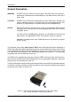
Introduction 1 INTRODUCTION Packaging Information The StorCase Technology Data Express® system is shipped in a container designed to provide protection and prevent damage during shipment. The Data Express unit was carefully inspected before and during the packing procedure at the factory. Bent or broken connectors, or evidence of other damage to the Data Express should be reported to the shipper immediately. Refer to Figure 1 for the package contents.
2 Introduction Package Contents WARNING: DO NOT lose your electronic security keys! StorCase does not provide duplicate keys, and assumes no responsibility for lost data resulting from lost or stolen keys. The DE110 package contents include the following items. If any item is missing or damaged, contact your StorCase dealer for a replacement. Accessory Bag Electronic Security Keys (128-bit shown) DE110 Carrier and Receiving Frame Data Express Encrypted PATA Removable Enclosure Carrier & Rec.
Introduction 3 General Description WARNING: DO NOT lose your electronic security keys! StorCase does not provide duplicate keys, and assumes no responsibility for lost data resulting from lost or stolen keys. CAUTION: DO NOT insert the electronic security key into any FireWire port! Doing so can result in damage to the key! StorCase does not provide duplicate keys, and assumes no responsibility for lost data resulting from damaged keys.
4 Introduction This User's Guide describes the steps required to install the DE110 removable enclosure inside a computer peripheral bay or external expansion chassis. This guide supplements documentation provided with the host computer system, operating system, and the drive to be installed within the carrier. Features: Incorporates NIST* and CES**-certified DES and TDES algorithms One (1) removable low-profile drive carrier for 3.
Introduction 5 Receiving Frame Front Panel Key Lock/Drive Power Switch (Figure 3) - Performs three functions. The key switch assures proper seating of the drive carrier within the receiving frame, turns power to the drive carrier ON and OFF, and prevents unauthorized removal or installation of the carrier. For the computer to access data on the disk drive, the key must be turned counterclockwise to the locked position.
6 Introduction Carrier Removed from Receiving Frame Security Key Error Carrier Installed (Unlocked) Carrier Installed (Locked) Activity Indicator Encryption Mode is BYPASSED (Security Disabled) The number "1" shown above is for illustration purposes only. It can be 0 (for Master) or 1 (for Slave).
Introduction 7 Mode of Operation There are two (2) modes of operation: 1. Encryption/Decryption Mode (default): Entire disk (including boot sector and OS) is encrypted/decrypted with real-time performance. Refer to section "Electronic Security Key" for further information. 2. Bypass Mode: Disables Encryption/Decryption mode. To change the mode of operation, refer to section "Configuration Switches" for further information.
8 Introduction Configuration Switch Settings Switch 1: Enables either Bypass or Encrypt/Decrypt operation mode. Default mode is Encrypt/Decrypt. Operation Mode Bypass ON =Up Encryption/Decryption OFF =Down [ Default ] Switches 2, 3 & 4 : Configure drive data rate (66/100/133 MHz). Default rate is 100 MHz.
Introduction 9 Electronic Security Key WARNING: DO NOT lose your electronic security keys! StorCase does not provide duplicate keys, and assumes no responsibility for lost data resulting from lost or stolen keys. CAUTION: DO NOT insert the electronic security key into your computer's FireWire port! Doing so can result in damage to the key! StorCase does not provide duplicate keys, and assumes no responsibility for lost data resulting from damaged keys.
10 Introduction Receiving Frame Rear Panel I/O Connector (JP1) - The input/output connector provides a standard interface for all IDE signals. DC Power Connector (P1) - A standard 4-pin DC power connector is used to accept DC power. Option Pins (W1) Master/Slave Selection Jumper (ID0 & ID1) - Master Drive designation (jumper is factory-installed on ID0). Change jumper position to Pins 3 & 4 (ID1) for Slave Drive designation.
Installation 11 INSTALLATION WARNING: DO NOT lose your electronic security keys! StorCase does not provide duplicate keys, and assumes no responsibility for lost data resulting from lost or stolen keys. CAUTION: DO NOT insert the electronic security key into any FireWire port! Doing so can result in damage to the key! StorCase does not provide duplicate keys, and assumes no responsibility for lost data resulting from damaged keys.
12 Installation Installing the Drive into the Carrier 1. Attach the DC power cable (from the Drive Carrier Board) to the drive (Figure 6). 2. Carefully insert the drive into the carrier. Slide the drive towards the Drive Carrier Board, so that the I/O connector on the drive mates with the connector on the Drive Carrier Board (Figure 7). Make sure that the DC power cable is not pinched. Turn the drive/carrier assembly over. 3. Fasten the drive into place with four (4) #6-32 Phillips F.H.
Installation 13 NOTE: Electronic security key can be stored here for easy access 1 Insert this end into the carrier first 2 Slide the cover towards the back of the carrier 3 Secure with #6-32 Phillips Flat Hd. screws (2 Total) Figure 8A: Drive Cover Installation Drive Cover Key Slot The electronic security key can be safely stored in slot located on the drive carrier cover (Figure 8B) for easy access. 1. Insert the security key into the slot by mounting onto the key peg first. 2.
14 Installation Installing the Receiving Frame The drive should be installed into the carrier before installing the receiving frame into the mounting bay of a computer or expansion chassis. 1. Turn OFF power to the computer. 2. Open the computer system according to the manufacturers instructions. If necessary, temporarily remove any expansion boards that may make installation difficult. 3. With the drive carrier locked in place inside the receiving frame, install the DE110 into the 5.
Installation 15 Spacer Plates (Optional) NOTE: Depending on the computer system, spacer plates may be positioned on the receiving frame to utilize either top or bottom row of side-mounting holes (Figure 10). The DE110 is designed to fit most computer systems with standard 5.25" peripheral slots. The installation of the spacer plates (provided) may or may not be necessary. Spacer Plate (2 Total) OR 0869 Figure 10: Spacer Plate Installation (Optional) Encrypted DE110 User's Guide - Rev.
16 Installation 5. Connect the I/O cable from the host adapter to the receiving frame. The Pin 1 indicator on the cable must be properly aligned. 6. Connect the power cable from the DC power supply in the computer or expansion chassis to the power connector on the DE110 receiving frame. Refer to Figure 6 for the DE110 receiving frame power connector location. 7. Replace any expansion boards that may have been removed earlier. Replace the system cover according to the manufacturers instructions. 8.
Installation 17 Identification of Carrier NOTES: Carrier labels are provided (Figure 11). For quick reference, configuration switch settings are indicated on the carrier labels. Use carrier labels (provided) to identify carrier (or drive content). Simply remove label from backing and affix to the top of the drive cover. For quick reference, configuration switch settings are indicated on the carrier labels.
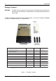
18 Installation I/O Connector JP1 The I/O connector (JP1) pin assignments are as follows: Table 1: AT/IDE Interface Signals Pin 01 03 05 07 09 11 13 15 17 19 21 23 25 27 29 31 33 35 37 39 Signal Host ResetHost Data 7 Host Data 6 Host Data 5 Host Data 4 Host Data 3 Host Data 2 Host Data 1 Host Data 0 Ground DMARQ DIOWDIORReserved Reserved IRQ 14 Host ADDR 1 Host ADDR 0 Host CS0DASP- I/O O I/O I/O I/O I/O I/O I/O I/O I/O O O O I O O O Notes Pin 02 04 06 08 10 12 14 16 18 20 22 24 26 28 30 32 34 36 38 40
Appendix A - Specifications/Dimensions 19 APPENDICES Encrypted DE110 User's Guide - Rev. A01 StorCase Technology, Inc.
20 Appendix A - Specifications/Dimensions Appendix A - Specifications/Dimensions The following specifications and dimensions are for reference only. Environmental Specifications Operating Storage Ambient Temperature Relative Humidity (1) 0° C to 50° C 10% to 80% Altitude -1000 to 10,000 ft -305m to 3048m -40° C to 70° C 10% to 90% -1000 to 40,000 ft -305m to 12195m Shock 10g 60g (1) (2) (2) Non-condensing with maximum gradient of 10% per hour. 11 msec pulse width 1/2 sine wave.
Appendix A - Specifications/Dimensions Receiving Frame with Carrier Installed 21 2.06 (52.3mm) 3.12 (79.2mm) 1.61 (40.9mm) 0.47 (11.9mm) 5.81 (147.6mm) 8.657 (219.89mm) 3.12 (79.2mm) Carrier Only 1.52 (38.6mm) 4.73 (120.1mm) 7.939 (201.65mm) 3.75 (95.3mm) 4.081 (103.66mm) 1.75 (44.5mm) Figure A-1: DE110 Physical Dimensions (Dimensions are for reference only) Encrypted DE110 User's Guide - Rev. A01 StorCase Technology, Inc.
22 Appendix B - Optional Accessories Appendix B - Optional Accessories Carrying Case 320FW_13 Figure B-1: Carrying Case The optional molded plastic carrying case is designed to transport one (1) DE110 carrier from one site to another in a safe, impact and moisture-resistant environment. Its compact dimensions, 10 long x 11 wide x 4.5 high, make it easy to carry and to store. The foam lining is contoured to fit a single Data Express carrier.
Reader's Comments 23 Reader's Comments Please take a few moments when your computer system is up and running to send us your ideas and suggestions for improving our products and documentation.
Reader's Comments CUT ALONG THIS LINE FROM BOTTOM TO TOP OF PAGE 24 FOLD ALONG THIS LINE AND STAPLE SHUT NO POSTAGE NECESSARY IF MAILED IN THE UNITED STATES B U S I N E S S R E P LY M A I L FIRST CLASS MAIL PERMIT NO. 10686 SANTA ANA, CA POSTAGE WILL BE PAID BY ADDRESSEE TECHNOLOGY CORPORATION 17600 NEWHOPE STREET FOUNTAIN VALLEY CA 92708-9885 StorCase Technology, Inc. Encrypted DE110 User's Guide - Rev.