VFC Radiant & Convector Fire Range With upgradeable control valve Instructions for Use, Installation and Servicing For use in GB, IE (Great Britain and Eire) This appliance has been certified for use in countries other than those stated. To install this appliance in these countries, it is essential to obtain the translated instructions and in some cases the appliance will require modification. Contact Gazco for further information. IMPORTANT The chimney must be swept before installation.
CONTENTS VFC RADIANT 8300UC P8300UC 16” 16” VFC CONVECTOR 8420UC P8420UC 16” 16” VFC LOW CONVECTOR 8461UC P8461UC 16”LL 16”LL 8301UC 16”RD 8421UC 16”RD 8463UC 16”RD LL P8301UC 16”RD P8421UC 16”RD P8463UC 16”RD LL 8305UC 18” 8425UC 18” 8466UC 18”LL P8305UC 18” P8425UC 18” P8466UC 18”LL 8310UC 22” 8430UC 22” 8471UC 22”LL P8310UC 22” P8430UC 22” P8471UC 22”LL Commissioning Check List PAGE 3 user instructions 4 instaLlation Instructions Technical Specificati
APPLIANCE COMMISSIONING CHECKLIST IMPORTaNT NOTICE Explain the operation of the appliance to the end user, hand the completed instructions to them for safe keeping, as the information will be required when making any guaranteed claims. FLUE CHECK Pass 1. Flue is correct for appliance 2. Flue flow test 3. Spillage test Fail GAS CHECK 1. Gas soundness & let by test 2. Standing pressure test mb 3.
USER INSTRUCTIONS 2.7 If the pilot will not light after repeated attempts, contact the retailer or installer from whom the appliance was purchased. 1. general 2.8 Turn the right hand control to point to main burner ( appliance can now be controlled using the left hand control knob. 1.1 Installation and servicing must only be carried out by a competent person. 1.
USER INSTRUCTIONS 7. ARRANGEMENT OF FUEL BED COMPONENTS 2 ADVICE ON HANDLING AND DISPOSAL OF FIRE CERAMICS The fuel effect and side panels in this appliance are made from Refractory Ceramic Fibre (RCF), a material which is commonly used for this application. AR0416 Protective clothing is not required when handling these articles, but we recommend you follow normal hygiene rules of not smoking, eating or drinking in the work area and always wash your hands before eating or drinking.
USER INSTRUCTIONS 16” AND REDUCED DRAUGHT COAL LAYOUT 7 7.4 Curved fronts (Holyrood and Richmond) Place 5 large coals onto the front coal moulding ensuing that they rest against the front. Place 2 small coals on to the front coal, 1 at each end. See Diagram 4. 4 AR1118 7.8 Place the remaining 4 small coals on top of the others so that they form a bridge between the second and third rows. See Diagram 8. 8 AR1115 7.
USER INSTRUCTIONS 10 13 AR1124 AR1121 22” COAL LAYOUT 7.11 Place 6 large coals onto the flame baffle fingers. See Diagram 11. 7.14 All fronts - place 8 large coals onto the front coal moulding ensuring that they rest against the front. Place 2 small coals on to the front coal, 1 at each end. See Diagram 14. 11 14 AR1122 7.12 Place 5 large coals so that they form a bridge between the other 2 rows, then 2 small coals, 1 at each end. Place 5 large coals at the back of the fire. See Diagram 12.
USER INSTRUCTIONS 10.’RUNNING IN’ 16 The surface coating on the coals used in your GAZCO fire will ‘burn off’ during the first few hours of use, producing a harmless and temporary odour. This will disappear after a short period of use. If the odour persists, ask your installer for advice. 11. SERVICING AR1128 This fire must be serviced every 12 months by a qualified Gas Engineer.
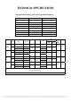
TECHNICAL SPECIFICATION tHESE INSTRUCTIONS COVER THE FOLLOWING MODELS: VFC RADIANT Model 16 RD 8420UC 16” 8461UC 16”LL P8300UC 16” P8420UC 16” P8461UC 16”LL 8301UC 16”RD 8421UC 16”RD 8463UC 16”RD LL P8301UC 16”RD P8421UC 16”RD P8463UC 16”RD LL 8305UC 18” 8425UC 18” 8466UC 18”LL P8305UC 18” P8425UC 18” P8466UC 18”LL 8310UC 22” 8430UC 22” 8471UC 22”LL P8310UC 22” P8430UC 22” P8471UC 22”LL Working Pressure Aeration I2H Natural Gas (G20) 20 mbar 12N I3+ Bu
INSTALLATION INSTRUCTIONS SITE REQUIREMENTS The flue must be installed in accordance with all local and national regulation and the current rules in force. 3.1 Ventilation requirements differ according to the model. Minimum permanent effective free air requirements - if this is the sole gas appliance in the room - are as follows: 1.FLUE AND CHIMNEY REQUIREMENTS 1.1 The chimney or flue system must comply with the rules in force, and must be a minimum of 178mm (7") in diameter. 1.
INSTALLATION INSTRUCTIONS SITE REQUIREMENTS 1A VFC Radiant 1B VFC Convector 4.4 The appliance must be firmly fixed to the hearth. Fasteners are provided for this purpose. 4.5 Ensure that no naked flame or incandescent part of the fire bed projects beyond the vertical plane of the fireplace opening. 4.6 The appliance must not be installed in any room that contains a bath or shower. 4.7 Ensure clearances to combustible materials - see Diagram 2.
INSTALLATION INSTRUCTIONS INSTALLATION IMPORTANT: ENSURE THAT THE APPLIANCE IS CORRECTLY ADJUSTED FOR THE GAS TYPE AND CATEGORY APPLICABLE IN THE COUNTRY OF USE. REFER TO DATABADGE AND TECHNICAL SPECIFICATIONS AT THE FRONT OF THE BOOKLET. FOR DETAILS OF CHANGING BETWEEN GAS TYPES, SECTION 9, SERVICING. 4. INSTALLATION - RADIANT FIRES 4.1 Fix the rear leg strap. See Diagram 1. 1 1. CONTROL UPGRADE 1.1 Your fire is fitted with a control valve that can be easily upgraded to battery powered remote control.
INSTALLATION INSTRUCTIONS INSTALLATION 4.6 Check the gas connections to the fire are sound. Light the fire and check all joints on the appliance. 6 4.7 Check the appliance running pressure is correct. See databadge. 4.8 Fit the fret to the fire front using two screws. See Diagram 4. 4 AR0200 Note: Gas pipes passing through masonry must be protected. 5.3 If the isolation tap is to be fitted under the fire, the GAZCO GC0060 provides a neat and easy solution. See Diagram 7A. AR0311 7 5.
INSTALLATION INSTRUCTIONS INSTALLATION 11 5.6 Carefully fit the convector box, feeding the piping through into the box. Secure the box to the wall, through the flange or base ensuring that the box is square in the opening. Any undulations or gaps between the convector box and the wall should be filled with a non-combustible material. Do not use silicone as it makes future removal almost impossible. 5.7 Refit the fire assembly and front air guide back into the convector box. See Diagram 9. 9 AR0303 5.
INSTALLATION INSTRUCTIONS INSTALLATION NOTE: CERAMIC PARTS ARE FRAGILE. 15 6.1 Position the flame baffle on the rear of the tray. See Diagram 13 arrow B. 6.2 Position the front coal, make sure it sits flat onto the burner skin. See Diagram 13 arrow C. 13 AR1116 6.6 Place 5 large coals onto the flame baffle fingers. See Diagram 16. 16 AR2190 6.3 Place the coals following the appropriate Diagrams and Instructions: 16” AND REDUCED DRAUGHT COAL LAYOUT AR1117 6.
INSTALLATION INSTRUCTIONS INSTALLATION 18” COAL LAYOUT 22 6.9 Curved fronts (Holyrood) - Place 6 large coals onto the front coal moulding ensuring that they rest against the front. Place 2 small coals onto the front coal, 1 at each end. See Diagram 19. 19 AR1129 6.13 Place the remaining 5 small coals on top of the others so that they form a bridge between the second and third rows. See Diagram 23. AR1120 23 6.
INSTALLATION INSTRUCTIONS INSTALLATION 25 AR1127 6.16 Place 7 large coals so that they form a bridge between the other 2 rows, and 2 small coals, 1 at each end. Place 6 large coals at the back of the fire. See Diagram 26. 26 AR1123 27 AR1128 6.17 Place the remaining 6 small coals on top of the others so that they form a bridge between the second and third rows. See Diagram 27. 7. LIGHTING 7.1 Full instructions are given in the Users Section.
INSTALLATION INSTRUCTIONS COMMISSIONING 1. COMMISSIONING 1.1 Close all windows and doors to the room, check all controls, and allow fire to burn on maximum for 5 minutes. Test for spillage of flue products using a smoke match. For standard VFC fires, pass the lighted smoke match along the top front edge just inside the opening or canopy. For the RD VFC only, hold the lighted smoke match centrally inside the flue opening. See Diagram 1 for Radiant fires and 2 for Convector fires. 1 AR0187 2 AR0179 1.
SERVICING INSTRUCTIONS SERVICING REQUIREMENTS This appliance must be serviced at least one a year by a competent person. FLAME FAILURE FUNCTIONAL CHECK PILOT WILL NOT STAY LIT OR FIRE GOES OUT 1. servicing requirements If the appliance goes out in use continually, this may mean that the oxygen depletion sensor has been activated. The appliance should not be used until the cause has been found and rectified. 1.
NO 20 YES NO NO YES NO YES NO Has the system got any air in it? YES Is the gas pressure correct? YES Is the gas turned on to the appliance? NO Will the pilot light with a match YES Is the control being operated correctly? NO Does the pilot light? See “NO SPARK” chart* System OK There is a blockage in the system, check the inlet test point, the mag seating, valve and pilot filter.
SERVICING INSTRUCTIONS REPLACING PARTS 2.5 Disconnect the ignition lead from the gas valve and the pilot. See Diagram 4 arrow A. The following part can be serviced without removing the fire. 2. IGNITION LEAD 4 2.1 Turn off the gas supply at the isolation device. 2.2 Remove the fret. See Diagram 1. 1 AR0305 2.6 Replace with a new ignition lead following the same route as the old one. Replace the valve cover and the pilot assembly. 2.7 Check the operation of the new ignition lead. AR0311 2.
SERVICING INSTRUCTIONS REPLACING PARTS 5. ODS PILOT UNIT 7 Note: The pilot unit on the appliance is a non serviceable unit due to the complex nature of its manufacture. Replacement of the complete unit must be carried out if one of the following items becomes faulty: Pilot injector Ignition electrode Thermocouple 5.1 Carry out operations (a) to (d), Section 4. AR0097 5.2 Gently pull the ignition lead off the electrode. See Diagram 5 arrow A. 5.
INSTALLATION INSTRUCTIONS REPLACING PARTS 7.5 Replace the thermocouple and check for gas leaks. 6.4 To release the right hand side of the control cover insert the narrow blade screwdriver into the slot shown in Diagram 10, lever it gently and pull from the right hand side at the same time. The cover will now come off, there is a small cylindrical metal spacer inside the cover. This must be kept and replaced on the fixing screw during re-assembly. 7.
SPARES PARTS LIST MANUAL FIRES RD 16 18 22 CERAMIC PARTS Front Coal LH CE0151 CE0152 CE0153/54 Flame Baffle CE0119 CE0120 CE0121 Burner Skin CE0155 CE0156 CE0157 Coal Set CE0394 CE0395 CE0396 IN0043 IN0042 Convector Side Cheek LH CE0158 Low Convector Side Cheek LH CE0160 Convector Side Cheek RH CE0159 Low Convector Side Cheek RH CE0161 Natural Gas Parts Main Injector IN0007 IN0005 Pilot Assembly PI0036 Aeration Adjuster PI0044 GZ3461 Gas Valve GZ3463 GZ3464 GC0088
SERVICE RECORDS 1ST SERVICE 2ND SERVICE Date of Service:........................................................................... Date of Service:........................................................................... Next Service Due:....................................................................... Next Service Due:....................................................................... Signed:........................................................................................
Gazco Limited, Osprey Road, Sowton Industrial Estate, Exeter, Devon, England EX2 7JG Technical Customer Services (01392) 261950 Fax: (01392) 261951 E-mail: technicalserviceds@gazco.