Marlborough & Stockton Coal Effect Stove Range Conventional Flue With upgradeable control valve Instructions for Use, Installation and Servicing For use in GB, IE (Great Britain and Eire) This appliance has been certified for use in countries other than those stated. To install this appliance in these countries, it is essential to obtain the translated instructions and in some cases the appliance will require modification. Contact Gazco for further information.
CONTENTS COVERING THE FOLLOWING MODELS MARLBOROUGH - 8560 - P8560 - 8564 - P8564 - 8568 - P8568 STOCKTON - 8573 - P8573 - 8574 - P8574 PAGE APPLIANCE COMMISSIONING CHECKLIST 3 USER INSTRUCTIONS 4 INSTALLATION INSTRUCTIONS 10 Technical Specifications 10 Site Requirements 11 Installation 12 Commissioning 17 SERVICING INSTRUCTIONS 18 Servicing Requirements 18 Fault Finding 19 How to replace parts 20 Basic spare parts list 24 Service records 25 2
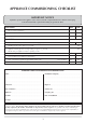
APPLIANCE COMMISSIONING CHECKLIST IMPORTANT NOTICE Explain the operation of the appliance to the end user, hand the completed instructions to them for safe keeping, as the information will be required when making any guaranteed claims. FLUE CHECK 1. Flue is correct for appliance 2. Flue flow test 3. Spillage test PASS FAIL Y/N Y/N GAS CHECK 1. Gas soundness & let by test (Please circle Y / N as appropriate) 2. Standing pressure test in figures (e.g. 20 mb) mb 3.
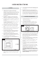
USER INSTRUCTIONS 1.12 In all correspondence, please quote the appliance type and serial number which can be found on the databadge at the rear of the stove. 1.13 This product is guaranteed for 2 years from the date of installation, as set out in the terms and conditions of sale between Gazco and your local Gazco dealer. Please consult with your local Gazco dealer if you have any questions. In all correspondence always quote the Model No. and Serial No.
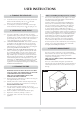
USER INSTRUCTIONS 3. TURNING THE STOVE OFF 3.1 3.2 Advice on Handling and disposal of fire ceramics 5.7 The fuel effect and side panels in this appliance are made from Refractory Ceramic Fibre (RCF), a material which is commonly used for this application. Protective clothing is not required when handling these articles, but we recommend you follow normal hygiene rules of not smoking, eating or drinking in the work area and always wash your hands before eating or drinking.
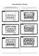
USER INSTRUCTIONS 6.4 Small Marlborough and Stockton 6 Place five of the loose round coals on the front coal so that they lean against the flame baffle, in between the fingers. Place the two rectangular coals behind the round coals, one at each side, see diagram 7. 6.1 Place the flame baffle onto the burner and push up against the rear tray lip, see diagram 4. 7 4 AR0362 AR0359 6.2 6.
USER INSTRUCTIONS 6.7 Ensure that the fibreglass seal on the back of the door is intact, locate the door on the four studs and slide back to the firebox. Secure in place using the four dome nuts and the tool supplied, do not over tighten the nuts, see diagram 10. Keep the tool with these instructions for future use. 6.10 Place three large coals on the front coal so that they lean against the flame baffle, and the four large coals on the flame baffle so that they sit on the fingers, see diagram 13.
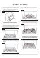
USER INSTRUCTIONS 6.13 Ensure that the fibreglass seal on the back of the door is intact, locate the door on the four studs and slide back to the firebox. Secure in place using the four dome nuts and the tool supplied, do not over tighten the nuts, see diagram 16. Keep the tool with these instructions for future use. 6.16 Place three large coals on the front coal so that they lean against the flame baffle and four large coals on the flame baffle so that they sit on the fingers, see diagram 19.
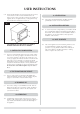
USER INSTRUCTIONS 6.19 Ensure that the fibreglass seal on the back of the door is intact. Locate the door on the four studs and slide back to the firebox. Secure in place using the four dome nuts and the tool supplied, do not over tighten the nuts, see diagram 22. Keep the tool with these instructions for future use. 11. VENTILATION 11.1 Any purpose provided ventilation should be checked periodically to ensure it is free from obstruction. 22 12. INSTALLATION DETAILS 12.
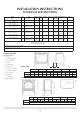
INSTALLATION INSTRUCTIONS TECHNICAL SPECIFICATION Model CAT. Small: Gas Type Working NOX Pressure Class Aeration Injector Gas Rate Input kW (Gross) m3⁄h Country High Low 0.433 4.55 Gross 2.5 Gross GB,IE 120 0.173 0.131 4.60 Gross 2.5 Gross GB,IE ø11 mm 375 0.639 6.60 Gross 3.25 Gross GB,IE 5 ø15.5 x 2 170 0.237 0.18 6.30 Gross 3.25 Gross GB,IE 20 mbar 5 ø13 mm 560 0.848 5 ø15.5 x 2 ø13.0 x 1 240 0.35 0.266 4.0 Gross 4.0 Gross GB,IE I3+ LPG Propane G31 37 mbar 8.
INSTALLATION INSTRUCTIONS SITE REQUIREMENTS 3.3 1. FLUE AND CHIMNEY REQUIREMENTS Soft copper tubing and soft soldered joints can be used but must not be closer than 50mm to the base of the tray. A means of isolating the gas supply to the appliance must be provided, independent of any appliance control. All supply gas pipes must be purged of any debris that may have entered, prior to connection to the appliance. 3.4 1.1 1.2 1.3 1.4 1.
INSTALLATION INSTRUCTIONS INSTALLATION IMPORTANT: ENSURE THAT THE APPLIANCE IS CORRECTLY ADJUSTED FOR THE GAS TYPE AND CATEGORY APPLICABLE IN THE COUNTRY OF USE. REFER TO DATABADGE AND TECHNICAL SPECIFICATIONS OF THIS BOOKLET. FOR DETAILS OF CHANGING BETWEEN GAS TYPES REFER TO SERVICING INSTRUCTIONS, REPLACING PARTS. pull. If this occurs a minimum of 10 minutes should be allowed before trying to relight.
INSTALLATION INSTRUCTIONS INSTALLATION There is a cutout in the RH rear leg to enable a direct straight connection to be made to the rear of the stove. See diagram 3. A gas soundness check must be completed up to the gas inlet connection. Check the pull of the flue system by applying a lighted smoke pellet to the flue system opening. If there is a definite flow into the chimney, proceed with the installation. If not, warm the chimney for a few minutes.
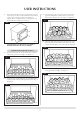
INSTALLATION INSTRUCTIONS INSTALLATION 6.2 Locate the rear panel against the spacer brackets and slide down so that it locates on the ledge of the flame baffle, see diagram 6. 6.5 6 Place four of the loose round coals behind the first row so that they sit on the fingers, the two outer coals should touch the rectangular coals, see diagram 9. 9 AR0360 6.3 AR0363 Locate the front coal between the heat shield and flame baffle so that its ends sit flat against the burner skin, see diagram 7. 6.
INSTALLATION INSTRUCTIONS INSTALLATION 6.11 Place two small coals at each end of the front coal so that they lean against the flame baffle, and a further two large coals on the flame baffle, one at each end, see diagram 15. Medium Marlborough and Stockton 8 6.8 Place the flame baffle onto the shelf at the rear of the tray and push up against the rear ledge, see diagram 12. 15 12 AR0368 6.12 Place five small coals along the rear of the flame baffle, resting against the rear ledge, see diagram 16.
INSTALLATION INSTRUCTIONS INSTALLATION 6.17 Place three small coals at each end of the front coal so that they lean against the flame baffle and a further four large coals on the flame baffle, two at each end, see diagram 21. Large Marlborough 21 6.14 Place the flame baffle onto the shelf at the rear of the tray and push up against the rear ledge, see diagram 18. 18 AR0373 6.18 Place six small coals along the rear of the flame baffle, resting against the rear ledge, see diagram 22. 22 AR0370 6.
INSTALLATION INSTRUCTIONS COMMISSIONING 1. COMMISSIONING 1.1 Close all openable doors and windows in the room. Ignite the stove and operate on maximum for 10 minutes. Remove the plastic sight plug from the right-hand side of the stove. Position a lighted smoke match just inside the draught diverter opening and check that all smoke is drawn into the opening. Watch through the viewing hole in the side of the casing. In restricted locations a mirror can be used. See diagram 1.
SERVICING INSTRUCTIONS SERVICING / FAULT FINDING CHARTS 1 1. SERVICING REQUIREMENTS 1.1 1.2 1.3 1.4 SYSTEM OK SEE 'NO SPARK' CHART There is a blockage in the system, check the inlet test point, the mag seating, valve and pilot filter. Purge the gas pipes and retry. No Has the system got any air in it? Yes Yes Yes Is the gas pressure correct? No Correct and retry. No 18 Check isolation tap and gas meter, retry. Check alignment of pilot burner head.
Replace the lead and, retry. No Is the electrode wire detached from the piezo in the valve? No Replace the electrode. Yes Yes Yes No No Correct and retry. Reset the pilot burner. Is the valve being operated correctly? Yes Replace the piezo and gas valve and retry. No Remove the electrode lead from the piezo. Operate the valve. Does a spark jump from the piezo to the valve body? Check for defective or damaged control knob spindle or cam operation.
SERVICING INSTRUCTIONS REPLACING PARTS 2.3 1. GENERAL 1.1 All principal components can be replaced without removing the stove from its installation but it is essential that the gas supply to the appliance is turned off at the isolation device before proceeding further. Loosen main injector nut on airbox and disconnect from injector, see diagram 3, A. 3 A 2. BURNER UNIT REMOVAL 2.1 Turn the gas supply off at the isolation device. Ensure the unit is cool.
SERVICING INSTRUCTIONS REPLACING PARTS 3. PILOT UNIT 3.1 4. IGNITION LEAD AND PIEZO Remove the burner module as described in Servicing Section 2 above. Carefully cut the cable ties holding the thermocouple to the pilot pipe. Remove the HT lead from the electrode, undo the two retaining screws and remove the pilot. See diagram 5. 4.1 Gain access to the back of the pilot assembly, (see section 2) and disconnect the ignition lead from the electrode.
SERVICING INSTRUCTIONS REPLACING PARTS 11 6. GAS VALVE 6.1 6.2 Turn the gas supply off at the isolation device. Disconnect the 2x8mm and 1x4mm gas pipe fittings at the back of the gas valve and also disconnect the thermocouple, see diagram 9. 9 AR0916 6.5 6.6 6.7 6.8 6.3 Disconnect the ignition lead from the gas valve. Undo the two bolts securing the gas valve to the appliance and remove the valve. Replace in reverse order. Check all joints for gas leaks.
SERVICING INSTRUCTIONS REPLACING PARTS 9.2 8. MAIN INJECTOR 9.3 8.1 Turn the gas supply off at the isolation device. Locate the main injector on the LH side of the airbox, undo the compression nut and pull the pipe clear of the injector body, see diagram 13A. Refit a new sensor ensuring the spacers are located between the sensor and the bracket. Replace the two leads.
SERVICING INSTRUCTIONS REPLACING PARTS 12. CONTROL UPGRADE See Installation, section 1. 13.
SERVICE RECORDS 1ST SERVICE 2ND SERVICE Date of Service:........................................................................... Date of Service:........................................................................... Next Service Due:....................................................................... Next Service Due:....................................................................... Signed:........................................................................................
Gazco Limited, Osprey Road, Sowton Industrial Estate, Exeter, Devon, England EX2 7JG Tel: (01392) 261999 Fax: (01392) 444148 E-mail: info@gazco.