Aspen, Chamonix & Tahoe Decorative Gas Basket Fires With upgradeable control valve Instructions for Use, Installation and Servicing For use in GB, IE (Great Britain and Eire) This appliance has been certified for use in countries other than those stated. To install this appliance in these countries, it is essential to obtain the translated instructions and in some cases the appliance will require modification. Contact Gazco for further information.
Covering the following models (P)8135**UC (P)8143**UC (P)8119**UC (P)8127**UC (P)8136**UC (P)8144**UC (P)8120**UC (P)8128**UC Please Note -** Will be replaced with the appropriate fuel effect suffix as follows: MC - Coal effect PB - Pebble effect GL - Glass granules L - Log effect DW - Driftwood effect CONTENTS PAGE APPLIANCE COMMISIONING CHECKLIST 3 USER INSTRUCTIONS 4 INSTALLATION INSTRUCTIONS 12 Technical Specifications 12 Site Requirements 13 Installation 15 Commisioning 22 SERVICING INS
APPLIANCE COMMISSIONING CHECKLIST IMPORTANT NOTICE Explain the operation of the appliance to the end user, hand the completed instructions to them for safe keeping, as the information will be required when making any guaranteed claims. FLUE CHECK PASS 1. Flue is correct for appliance 2. Flue flow test 3. Spillage test FAIL GAS CHECK 1. Gas soundness & let by test 2. Standing pressure test mb 3.
USER INSTRUCTIONS knob anticlockwise to increase the flame height and clockwise to decrease the flame height. THE YELLOW FLAMES WILL APPEAR WHEN THE FIRE HAS GAINED SUFFICIENT HEAT - TYPICALLY 10 TO 20 MINUTES. 1. GENERAL 1.1 1.2 1.3 1.4 Installation and servicing must only be carried out by a competent person. In all correspondence, please quote the appliance type and serial number, which can be found on the databadge located on a chain beneath the control valve.
USER INSTRUCTIONS 5. UPGRADING YOUR FIRE 5.1 5.2 5.3 5.4 7.1.4 Your fire is fitted with a control valve that can be easily upgraded to battery powered remote control. This upgrade can be fitted by anyone capable of simple DIY jobs and requires no special training. This upgrade can be obtained through your local Gazco stockist. STANDARD REMOTE CONTROL This remote control can control the fire after the pilot has been lit.
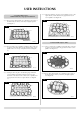
USER INSTRUCTIONS 7.4.2 Place 14 small coals or pebbles around the edge of the tray as shown, ensure that there are gaps between each coal or pebble. Place one on top of the pilot shield. See diagram 6. 7.3.3 Using the small beads, fill the fire to the top. See diagram 3. 3 6 AR1263 7.3.4 Smooth out the fire beads, it is important to ensure that the fire is completely filled, level to the top.
USER INSTRUCTIONS 7.5.4 Place the remaining 11 large coals or pebbles on top of the square blocks, ensure that there are gaps between each coal or pebble. See diagram 12. 7.5 Coal & Pebble Layout Medium Chamonix, Large Aspen & Chamonix 12 7.5.1 Place 15 large square blocks in a solid mass in the centre of the burner tray as shown, ensure they fit tightly together. See diagram 9. 9 AR1269 AR1266 7.6 Coal & Pebble Layout - Tahoe 7.5.
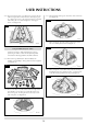
USER INSTRUCTIONS 17 7.6.3 Place one large coal or pebble on top of the pilot shield, then place 10 alternating large and small coals or pebbles around the perimeter of the fire. They should sit on the bottom row of small coals or pebbles and rest against the inner mass of square blocks. Place one small coal or pebble on top of the centre of the square blocks. See diagram 15. 8 15 7.7.2 Place the two logs (No.13) on top of the beads as shown. See diagram 18. AR1272 18 7.6.
USER INSTRUCTIONS 7.7.4 Place log (No. 7) along the LH side of the tray, log (No. 9) along the RH side of the tray and place logs (No. 8 and 11) along the front of the tray as shown. Place the cone (No. 14) on the LH side of the burnt log. See diagram 20. 7.8.2 Place the two logs (No.13) on top of the beads as shown. See diagram 23. 23 20 AR1278 AR1276 7.7.5 Place the large log (No. 6) so that it rests on top of the rear and front logs to the LH side, Place log (No. 7) on the RH side and log (No.
USER INSTRUCTIONS 7.8.5 Place one large log (No. 6) so that it rests on top of the rear and front logs to the LH side. Place the other large log (No. 6) so that it rests on top of the rear and front logs on the RH side and log (No. 8) so that it bridges the centre gap as shown. See diagram 26. 7.9.3 Place the burnt effect log (No. B1) in the centre of the tray. See diagram 29. 29 26 AR1283 7.9.4 Place one log (No. 8) in the centre so that it rests on the rear cone and the pilot shield. See diagram 30.
USER INSTRUCTIONS 7.9.6 Place the two thin logs (No. 12), one at each side sitting on the tray and resting against the previously positioned logs. Place one log (No. 9) at the LH rear resting on the base log, and one log (No. 8) at the RH rear. See diagram 32. 8. OXYGEN DEPLETION SENSOR 8.1 32 The appliance is fitted with an oxygen sensitive pilot system that will act to cut off the gas supply to the fire should the oxygen in the room fall below its normal level.
G31 PROPANE G30 G31 G20 G30 G31 NATURAL BUTANE CHAMONIX PROPANE NATURAL BUTANE PROPANE ASPEN & MEDIUM & LARGE CHAMONIX & LARGE ASPEN G20 G30 G20 NATURAL BUTANE GAS CATEGORY GAS TYPE SMALL TAHOE MODEL 12 37 mb 29 mb 20 mb 37 mb 29 mb 20 mb 37 mb 29 mb 20 mb (mb) 3 * 15mm 3 *15mm 7.5mm 3 * 15mm 3 * 15mm 7.5 mm 3 * 15mm 3 * 15mm 7.5mm INLET AERATION PRESSURE SIZE 600 600 1600 400 400 1600 400 400 1100 20.5 15.7 8.3 25.3 20.0 5.4 21.1 16.3 9.
INSTALLATION INSTRUCTIONS SITE REQUIREMENTS 1.3 1. FLUE AND CHIMNEY REQUIREMENTS 1.1 1.4 The chimney or flue system must comply with the rules in force. Fireplace opening up to 450mm (18") wide by 600mm (24") high will usually work with a 175mm (7") diameter flue. Larger openings will require bigger flues. See diagram 1 as a guide. 1.2 1.5 1.6 1 D D The chimney or flue must be free from any obstruction.
INSTALLATION INSTRUCTIONS SITE REQUIREMENTS 4.8 4. APPLIANCE LOCATION 4.1 4.2 4.3 4.4 4.5 4.6 4.7 The following table indicates the minimum opening sizes for each model. In each case, a gap of 20mm has been allowed to both Left and Right of the basket. See diagram 3. 3 This appliance must stand on a non-combustible hearth that is at least 12mm thick. It must be fitted into a non-combustible opening. These appliances must be hearth mounted into a fireplace opening conforming to National Standards.
INSTALLATION INSTRUCTIONS INSTALLATION 3.3 IMPORTANT:ENSURE THAT THE APPLIANCE IS CORRECTLY ADJUSTED FOR THE GAS TYPE AND CATEGORY APPLICABLE IN THE COUNTRY OF USE. REFER TO DATABADGE AND TECHNICAL SPECIFICATIONS AT THE FRONT OF THE BOOKLET. FOR DETAILS OF CHANGING BETWEEN GAS TYPES REFER TO SERVICING SECTION 9. Remove both the decorative basket and fire, drill the marked holes and insert the rawplugs provided. Place the gas fire in position and secure to the hearth using the screws provided.
INSTALLATION INSTRUCTIONS INSTALLATION 5.1.8 Depending on the fuel effect that you have been supplied with, follow the correct section. 4. CONTROL UPGRADE 5.2 Glass Granules 4.1 4.2 4.3 4.4 Your fire is fitted with a control valve that can be easily upgraded to battery powered remote control. This upgrade can be fitted by anyone capable of simple DIY jobs and requires no special training. This upgrade can be obtained through your local GAZCO stockist.
INSTALLATION INSTRUCTIONS INSTALLATION 5.3.6 Ensure that no beads have fallen into the pilot area. 5.3.7 Ensure that the pilot shield is fitted correctly and that it fits tightly onto the edge of the tray. See diagram 5. 5.4.3 Starting at the front, place 14 alternating large and small coals or pebbles around the perimeter of the fire, they should sit on the bottom row of small coals or pebbles and rest against the inner mass of square blocks. See diagram 8. 5 8 AR0558 AR1264 5.4.
INSTALLATION INSTRUCTIONS INSTALLATION 5.5.2 Place 18 small coals or pebbles around the edge of the tray as shown, ensure that there are gaps between each coal or pebble. Place one on top of the pilot shield. See diagram 11. 5.6 Coal & Pebble Layout - Tahoe 5.6.1 Place 10 small coals or pebbles around the edge of the tray as shown, ensure that there are gaps between each coal or pebble. See diagram 14. 11 14 AR1267 AR1270 5.5.
INSTALLATION INSTRUCTIONS INSTALLATION 5.6.4 Place the remaining 4 large coals or pebbles on top of the square blocks, ensure that they lean against the central small coal or pebble and that there are gaps between each coal or pebble. See diagram 17. 5.7.3 Place the large log (No. 1) so that it sits on top of the previous two logs. Place the burnt effect log (No. B1) in the centre of the tray as shown. See diagram 20. 20 17 AR1275 AR1273 5.7.4 Place log (No. 7) along the LH side of the tray, log (No.
INSTALLATION INSTRUCTIONS INSTALLATION 5.8.3 Place the large log (No. 1) so that it sits on top of the previous two logs. Place the burnt effect log (No. A1) in the centre of the tray as shown. Place one log (No. 7) along each side of the tray, another log (No. 7) along the front LH side and a log (No. 8) along the front RH side of the tray. See diagram 25. 5.
INSTALLATION INSTRUCTIONS INSTALLATION 5.9.4 Place one log (No. 8) in the centre so that it rests on the rear cone and the pilot shield. See diagram 31. 5.9 Log & Driftwood Layout – Tahoe 31 It may be necessary to make small changes to the log positioning in order to achieve the most pleasing flame effect but the following guidelines should be followed. 5.9.1 Refer to the log identification chart and identify the numbers corresponding to the logs that have been supplied. See diagram 28. 28 AR1284 8 5.
INSTALLATION INSTRUCTIONS COMMISSIONING 6. COMMISSIONING 6.1 Close all windows and doors to the room, check all controls, and allow fire to burn on maximum for 5 minutes. Test for spillage of flue products using a smoke match. Pass the lighted smoke match along the top front edge just inside the opening or canopy. See diagram 34. 34 6.2 6.3 6.4 If the fire spills, run for a further 10 minutes and re-check.
SERVICING INSTRUCTIONS SERVICING / FAULT FINDING CHARTS 1. SERVICING REQUIREMENTS This appliance must be serviced at least once a year by a competent person. All tests must be serviced by best practice as described by the current CORGI recommendations. 1.1 Before any tests are undertaken on the appliance, conduct a gas soundness test for the property to ensure that there are no gas leaks prior to starting work. 1.
No 24 Yes No Yes No No Yes No Has the system got any air in it? Yes Is the gas pressure correct? Yes Is the gas turned on to the appliance? No Will the pilot light with a match? Yes Is the control being operated correctly? No Does the pilot light? SEE NO SPARK CHART SYSTEM OK There is a blockage in the system, check the inlet test point, the mag seating valve and gas filter. Purge the gas pipes and retry. Correct and retry. Check isolation tap and gas meter, retry.
Yes 25 Change the ODS unit. No Will pilot stay alight? Is thermocouple connection good in back of valve? Problem is with the pipework or fittings which lead to the fire. Correct and retry. SYSTEM OK Change mag unit. No Will pilot stay alight? No No No Yes Yes Replace ODS unit. Yes No No Is the pilot flame of the correct length? See diagram 13 in replacing parts section.
SERVICING INSTRUCTIONS REPLACING PARTS 2.3 To release the right hand side of the control cover insert a narrow blade screwdriver into the slot shown in diagram 3, lever it gently and pull from the right hand side at the same time. The cover will now come off, there is a small cylindrical spacer inside the cover, this must be kept and replaced on the fixing screw during re-assembly. 1. FIRE REMOVAL 1.
SERVICING INSTRUCTIONS REPLACING PARTS 2.5 replace with a new ignition lead following the same route as the old one. replace the valve cover and securing screw. check the operation of the new ignition lead. 2.6 6 3. PIEZO A 3.1 The piezo unit used on this appliance is not serviceable and unlikely to fail. If a new piezo is required it will be necessary to change the gas valve, refer to section 7. 4. ODS PILOT UNIT 4.1 4.2 Remove the fire, see section 1. Remove the pilot shield and place to one side.
SERVICING INSTRUCTIONS REPLACING PARTS 7. PRIMARY AERATION PLATE 5. MAGNETIC UNIT 5.1 Remove the thermocouple from the back of the control valve. See diagram 8 arrow B. 7.1 Locate the aeration plate on the underside of the airbox and remove the Nyloc nut, see diagram 9. When replacing the aeration plate, ensure that the hole in the aeration plate is correctly aligned to one of the holes in the underside of the airbox, replace the Nyloc nut.
SERVICING INSTRUCTIONS REPLACING PARTS 12 8. GAS VALVE 8.1 8.2 Remove the fire, refer to section 1. Disconnect the 2x8mm and 1x4mm gas pipe fittings at the back of the gas valve, arrow A and disconnect the thermocouple. See diagram 10 arrow B. 10 A B 8.5 8.6 8.7 8.8 Disconnect the ignition lead from the gas valve, see section 2. Undo the two screws securing the gas valve to the control bracket and remove the valve. Replace in reverse order.
SERVICING INSTRUCTIONS REPLACING PARTS 9. SHORT SPARES LIST COMMON COMPONENTS Control Valve Ignition lead Magnetic Unit Control Cover Upgrade Kit Pilot Shield (Standard) Pilot Shield (Glass Granules) Small Clay Beads (0.5 ltr) Small Clay Beads (1.0 ltr) Large Clay Beads (1.0 ltr) Large Clay Beads (2.
SERVICE RECORDS 1ST SERVICE 2ND SERVICE Date of Service:........................................................................... Date of Service:........................................................................... Next Service Due:....................................................................... Next Service Due:....................................................................... Signed:........................................................................................
Gazco Limited, Osprey Road, Sowton Industrial Estate, Exeter, Devon, England EX2 7JG Tel: (01392) 261999 Fax: (01392) 444148 E-mail: info@gazco.