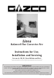
Linea Balanced Flue Convector Fire Instructions for Use, Installation and Servicing For use in GB, IE (Great Britain and Eire) This appliance has been certified for use in countries other than those stated. To install this appliance in these countries, it is essential to obtain the translated instructions and in some cases the appliance will require modification. Contact Gazco for further information. IMPORTANT Do not attempt to burn rubbish in this appliance.
CONTENTS COVERING THE FOLLOWING MODELS 8651EC P8651EC PAGE Appliance commissioning checklist 3 user instructions 4 instaLlation Instructions 8 Technical Specifications 8 Site Requirements 9 Installation 12 Commissioning 15 Servicing Instructions 16 Servicing Requirements 16 Fault Finding 16 How to replace parts 18 Basic spare parts list 24 Service Record 25 2
APPLIANCE COMMISSIONING CHECKLIST IMPORTaNT NOTICE Explain the operation of the appliance to the end user, hand the completed instructions to them for safe keeping, as the information will be required when making any guaranteed claims. FLUE CHECK Pass 1. Flue is correct for appliance 2. Flue flow test N/A 3. Spillage test N/A Fail GAS CHECK 1. Gas soundness & let by test 2. Standing pressure test mb 3.
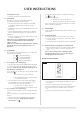
USER INSTRUCTIONS The pilot and main burner ignite and the remote is now in Manual Mode.
USER INSTRUCTIONS 2.3 • Press the SET button again to scroll past the settings for P1 and P1 With the time still flashing: • Press the UP arrow to alter the hour • Press the DOWN arrow to alter the minutes Once all four times are set press the OFF button or simply wait to complete programming. Turning the Linea Off • Press the Off button to extinguish the pilot TEMP MODE The display shows the current room temperature.
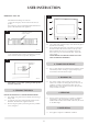
USER INSTRUCTION EMERGENCY SHUT OFF 5 If the batteries fail during use of the fire: • Move the emergency shut off switch to the OFF (O) position This emergency switch is located behind the slotted lower panel on the underside of the appliance: 3 Underside of appliance Access to switch AR1339 3.4 3.5 AR1341 • Use a ball point pen or narrow screwdriver to push the rocker switch to the OFF (O) position, Diagram 4 Use a damp cloth and warm soapy water. Ensure the glass is dry before re-assembling.
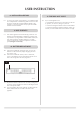
USER INSTRUCTION 8. installation details 8.1 11. FIRE WILL NOT LIGHT To assist in any future correspondence, your installer should have completed the commissioning sheet at the front of this book, this records the essential installation details of the appliance. In all correspondence always quote the Model number and Serial number. 11.
INSTALLATION INSTRUCTIONS TECHNICAL SPECIFICATION COVERING THE FOLLOWING MODELS 8651EC P8651EC Gas Model Linea NG Linea LPG Gas CAT. Type I2H Natural (G20) I3P Propane (G31) Working Aeration Injector Pressure 20mbar 2 x 8mm 1 x 7.5mm 37mbar 2 x 10mm Gas Rate Input kW (Gross) Nox Class Country 3.5 4 GB, IE 3.5 4 GB, IE m3/h High Low 1.7 0.50 5.25 1.2 0.20 5.
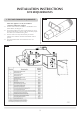
INSTALLATION INSTRUCTIONS SITE REQUIREMENTS 2 1. Flue and Chimney Requirements NOTE: This appliance can only be installed in conjunction with the flue supplied. The flue must be sited in accordance with BS5440: Part 1 (latest edition). See diagram 1. Any terminal which is less than 2 metres above any access (level ground, balcony or above a flat roof to which people have access) is to be fitted with a guard.
INSTALLATION INSTRUCTIONS SITE REQUIREMENTS 1.5 1.6 1.7 TIMBER FRAMED BUILDINGS It will be necessary to provide additional clearance when the flue passes through a wall containing any combustible materials so as to prevent a fire hazard. The hole through which the flue will pass, must have a steel sleeve which is positioned so that an air gap of at least 25mm is maintained between the outer surface of the flue, and any part of the sleeve.
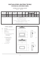
INSTALLATION INSTRUCTIONS SITE REQUIREMENTS 5 VETRO / PLANO / STEEL DIMENSIONS AR1327 4.4 All combustible materials must be removed from behind the appliance. See diagram 6. 6 Combustible material to be removed around centre line of flue. Shown as shaded area AR1328 4.5 The Linea may be mounted at any height, however, there must be a minimum clearance of 150mm (6") between the bottom edge of the appliance and the floor. To achieve this, the minimum flue height for each front is shown in diagram 7.
INSTALLATION INSTRUCTIONS INSTALLATION IMPORTANT: BEFORE THE APPLIANCE CAN BE OPERATED THE REMOTE HANDSET MUST BE TUNED TO THE CONTROL BOX SITUATED UNDER THE APPLIANCE. IF THIS PROCEDURE IS OMITTED THE APPLIANCE CAN ONLY BE LIT USING THE TOUCH PAD, SEE USER INSTRUCTIONS, 2B TOUCH PAD CONTROL. ENSURE THAT THE APPLIANCE IS CORRECTLY ADJUSTED FOR THE GAS TYPE AND CATEGORY APPLICABLE IN THE COUNTRY OF USE. REFER TO DATA BADGE AND THE TECHNICAL SPECIFICATIONS on page 8.
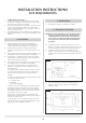
INSTALLATION INSTRUCTIONS INSTALLATION 2.7 The flue can now be cut to size. Measure the thickness of the wall, then deduct 12mm. This is the length required when measuring from the line on the flue label. See diagram 3. 6 3 A A AR1338 AR0630 2.8 DO NOT OVER TIGHTEN. DO NOT DEFORM THE REAR OF THE APPLIANCE. Attach the flue to the appliance and seal using the aluminium tape. See diagram 4. 2.13 Remove the nine screws retaining the glass frame, remove the frame and store in a safe place.
INSTALLATION INSTRUCTIONS INSTALLATION 2.15 Replace the glass frame; ensure the top of the frame is hooked on the tabs at the top of the appliance and replace the nine screws with the three longest screws used in the bottom fixing holes. Tighten from the top down. • automatically regulates the room temperature during the set periods TOUCH PAD CONTROL HAVE YOU PURGED THE GAS SUPPLY? 2.16 Connect the gas supply to the isolation device using 8mm pipe.
INSTALLATION INSTRUCTIONS COMMISSIONING Each of the four switches can be set to either one of two positions, in any combination. To re-code the handset: • Change the combination of how the DIP switches are set, Diagram 12 12 AR1936 Once the handset has a new code the control box needs to be reprogrammed: To access the control box see Servicing Instructions, Section 11 - Control Box. • Press and hold the reset button on the control box until you hear two signals.
SERVICING INSTRUCTIONS SERVICING / FAULT FINDING CHARTS REPLACE BATTERIES BEFORE ATTEMPTING TO RECTIFY ANY FAULTS. 1. SERVICING REQUIREMENTS IF THE FIRE DOES NOT WORK, BUT HAS WORKED IN THE PAST: • CHECK THE EMERGENCY SHUT OFF SWITCH ON THE BOTTOM OF THE APPLIANCE IS SWITCHED ON, SEE USER SECTION, PAGE 6 This appliance must be serviced at least once a year by a competent person. All tests must be serviced by best practice as described by the current CORGI recommendations. 1.
Replace the lead, retry. No Yes Is the valve being operated correctly? Check handset batteries are OK. Replace if required. Check handset is on manual. Check if handset lock is off. Check batteries to the control unit. Replace if required. Retry with handset and touch pad. Correct and retry. Check tab on pilot burner is not damaged. Either repair tab or replace pilot burner & retry Reconnect the lead and retry.
SERVICING INSTRUCTIONS REPLACING PARTS 2.4 1. GENERAL 1.1 2.5 All principal components can be replaced without removing the appliance from its installation, although it is essential that the gas supply to the appliance is turned off at the isolation device before proceeding further. If for any reason the flue has to be removed from the appliance, the seal must be replaced in the inner spigot.
SERVICING INSTRUCTIONS REPLACING PARTS 4 x 6 X = LPG 10 NG 15 AR1341 6.2 4.7 Reassemble in reverse order and replace the pilot gasket with a new one. Check for gas leaks. 4.8 Pull the ignition lead off the electrode and undo the retaining nut. See diagram 7. 7 5. Pilot injector 5.1 To gain access to the pilot pipe, it is easier if the thermocouple is removed first. To do this follow section 7. Undo the pilot pipe from the gas valve and from under side of the pilot burner. See diagram 5 arrow B.
SERVICING INSTRUCTIONS REPLACING PARTS 8 C 9. magnetic safety valve 9.1 9.2 9.3 10 AR1994 7.3 • Turn the gas off at the isolation device. • Remove the lower panel, Diagram 6 • Undo the thermocouple from the interrupter block and remove the two thermo current cables • Unscrew the interrupter block from the back of the valve. Diagram 10 Undo the thermocouple nut in the back of the pilot burner by half a turn. This will release the thermocouple.
SERVICING INSTRUCTIONS REPLACING PARTS appliance. Note the orientation of the injector on the pipe. 10.7 Reassemble in reverse order and check for gas leaks. 12 C 11. control box C 11.1 Remove the lower panel, Diagram 6 C C C 11.2 Press on/off switch retaining clips in and pop put the switch. Turn the switch to pass it through the retaining bracket. C C C C 11.3 Remove the two screws holding the control box to the bracket. Slide the control box to the right and remove from the bracket.
SERVICING INSTRUCTIONS REPLACING PARTS 14.1 Remove the outer decorative front, refer to the instructions supplied with the front. (FOR VETRO, PLANO AND STEEL FRAMES, MAKE SURE THAT THE TOUCHPAD IS REMOVED FROM THE HARNESS BEFORE FRAME REMOVAL) 14.2 Remove the lower panel. See diagram 6 above. 14.3 Disconnect the gas pipe at the isolation device. See diagram 17 arrow B. 12. gas VALVE 12.
SERVICING INSTRUCTIONS REPLACING PARTS 19 AR1345 14.7 Disconnect the touch pad from the harness (DESIGNIO FRAME ONLY) 14.8 Disconnect the ignition lead from the electrode. 14.9 Remove the thermocouple. See diagram 20 arrow C. 14.10 Remove the pilot pipe and ensure the pilot injector is kept safe, Diagram 20, Arrow D 20 D C F E F AR1994 14.11 Remove the injector feed pipe from the valve, Diagram 20, Arrow E. 14.
SERVICING INSTRUCTIONS REPLACING PARTS 15.
SERVICE RECORDS 1ST SERVICE 2ND SERVICE Date of Service:........................................................................... Date of Service:........................................................................... Next Service Due:....................................................................... Next Service Due:....................................................................... Signed:........................................................................................
Gazco Limited, Osprey Road, Sowton Industrial Estate, Exeter, Devon, England EX2 7JG Tel: (01392) 261999 Fax: (01392) 444148 E-mail: info@gazco.