
user manual


RCC130H-CRACK SAW OPERATION AND PARTS MANUAL REV #1 (11/18/04) PAGE 34
MAINTENANCE/SERVICE
c) If the belt tension and alignment are within
specifications, torque the engine/electric motor
attachment capscrews to 35 ft lbs (47 N.m).
d) Recheck V-belt tension and alignment.
10) Reinstall the belt guard to the main frame. Install
the flat washers and self locking hexagon nuts.
Determine that all safety related decals affixed to the
belt guard are fully readable. If any decal is not fully
readable, replace with a factory approved
replacement part only.
11) Reconnect the engine spark plug wire.
DANGER
UNEXPECTED MACHINE START UP CAN
RESULT IN PROPERTY DAMAGE AND/OR
PERSONAL INJURY.
INSTALLING REPLACEMENT BEARINGS ON
THE ARBOR SHAFT.
Application: All Models.
Tools Required:
2 each, 9/16 inch wrenches.
1 each, 3/4 inch wrench.
1 each, 5/32 inch Allen wrench.
1 each, pliers for large, external type snap rings.
1 each, shop press.
Parts Required:
2 each, PN 5208-2RS sealed bearings.
1 each, container of bearing and shaft locking grade,
anaerobic adhesive/sealant.
1 each, PN 5160-156 snap ring (if required).
1 each, PN CS8-0230 bearing block (if required).
1 each, PN CS8-0030 arbor shaft (if required).
1) Position the Crack Saw on a suitable work
surface with the V-belt approximately at waist level.
2) If the Crack Saw is powered by an engine,
disconnect the engine spark plug wire. If powered by
an electric motor, disconnect the extension cord or
Crack Saw from the power source. If the Crack Saw
is equipped with a Propane converted engine, the
Propane cylinder must be removed from the main
frame to better facilitate the maintenance process.
Determine that the Propane cylinder is fully closed
before uncoupling the hose. Secure in a proper
storage area.
3) Using the 9/16 inch wrenches, remove the belt
guard from the main frame. Clean the inside of the
belt guard with an appropriate solvent. Check for
signs of wear and damage. Secure in a proper
storage area.
CAUTION
Observe all applicable safety precautions for the
solvent.
4) Remove the V-belt and arbor shaft pulley. Refer
to INSTALLING A REPLACEMENT V-BELT OR
PULLEY for specific information. Remove the blade
guard from the main frame. Clean the interior and
exterior surfaces of the blade guard with an
appropriate solvent. Check for signs of wear and
damage.
5) Using the 3/4 inch wrench, remove the bearing
block/arbor shaft from the main frame. Clean the
arbor shaft/bearing block assembly with an
appropriate solvent. Check for signs of wear and
damage.
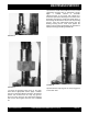
6) Position the bearing block/arbor shaft assembly
on a suitable work surface. Use the snap ring pliers
to remove the snap ring. FIGURE 40.
CAUTION
Wear safety glasses and other appropriate safety
apparel when removing the snap ring or
performing any work with an arbor press.
Caution all onlookers about the possibility of
flying debris and personal injury.
7) Using the Allen wrench, remove the Allen screws
that retain the hub body to the arbor shaft. If the hub
body does not freely remove itself from the arbor
shaft, position the assembly in a suitable arbor
press. FIGURE 41. The hub can be removed by
pressing the hub body from the arbor shaft. As the
hub body separates from the arbor shaft, the arbor
shaft/bearing block assembly can fall directly to the
work surface.