
user manual


MQ STOW MS20H/MS20E MIXER — PARTS & OPERATION MANUAL — REV. #3 (08/10/06) — PAGE 17
MS20H/MS20E MIXER — CONTROLS
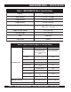
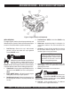
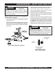
Figure 4. Mixer Components
1. Tires Ply — The tire ply (layers) number is rated in letters;
This mixer uses 13-inch 4-ply tires.
2. Engine Cover — Lift this cover to gain access to the engine
compartment.
3. Belt Slip Lever — When starting this lever should be
move upward and to the left. For mixing place the lever in
the down position. See attached decal located adjacent to
lever.
4. ON/OFF Switch (electric) — This switch is provided on
mixers with electric motors. To gain access to this switch,
lift the engine cover. When activated it will shut down the
electric motor.
5. ON/OFF Switch (gasoline) — This switch is provided on
mixers with gasoline
engines only and is located on the
side of the engine cover. When activated it will shut down
the engine.
6. Latch — Use this latch to secure the engine compartment
cabinet.
7. Safety Grill Lock Handle — To prevent injury to hands
and arms, the safety grill should ALWAYS be locked when
the mixing of plaster or mortar is required. Also when
transporting the mixer the safety grill should be locked.
The safety grill should only be un-locked when cleaning
of the blades and drum is required.
Figure 4 illustrates the basic components and controls of
the MS20H/MS20E mixer
8. Mixing Paddles — Used in the mixing of material. This
unit uses four different types of paddles to provide a fast
uniform mix.
9. Bag Cutter— This feature allows compound mixing bags
to be opened easily, therefore allowing the contents of the
bag to fall directly into the mixing drum.
10. Safety Grill — Provided for operator safety. This safety
grill is designed to keep hands and solid objects out of the
mixing drum when in use. This grill should be closed at all
times when mixer is in use. DO NOT remove the grill or
grill opening bar. Keep the grill clean by washing it down
daily.
11. Dump Handle — Pull this handle downward to dump the
contents of the drum. Push the handle upward to return
the drum to its vertical position.
12. Pivot Point/Zerk Fitting — There is, on each end of the
mixing drum a zerk grease fitting. These fittings lubricate
the dumping mechanism. Lubricate both fittings at least
twice a week.
13. Dump Handle Release Pin — Pull this pin outward
(spring loaded) to release the drum, then pull down on the
dump handle to place the drum in the dump position. When
drum is in dump position, pin will automatically lock drum.
14. Tow Bar/Coupler — This mixer uses a 2-inch coupler or
pintle
15. Safety Chain — This mixer uses a 3/16-inch thick, 72-
inches long zinc-plated saftey chain.
ALWAYS
connect
the safety chain when towing.
16. Steel Mixing Drum — Mixing materials such as mortar,
plaster are to be placed into this drum for mixing. Always
clean the drum after each use.
17. Chock Blocks — Place these blocks (not included as
part of the mixer package) under each mixer wheel to
prevent rolling.