OPERATION AND PARTS MANUAL STR36SP RIDE-ON POWER TROWEL HONDA GX670TAF 24 HP ENGINE Revision #0(09/16/11) To find the latest revision of this publication, visit our website at: www.multiquip.com THIS MANUAL MUST ACCOMPANY THE EQUIPMENT AT ALL TIMES.
PROPOSITION 65 WARNING Engine exhaust and some of its constituents, and some dust created by power sanding, sawing, grinding, drillingandotherconstructionactivities contains chemicals known to the State of California to cause cancer, birth defects and other reproductive harm. Some examples of these chemicals are: Leadfromlead-basedpaints. Crystallinesilicafrombricks. Cementandothermasonryproducts. Arsenicandchromiumfromchemically treatedlumber.
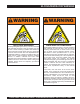
SILCOSIS/RESPIRATORY WARNINGS WARNING WARNING SILICOSIS WARNING RESPIRATORY HAZARDS Grinding/cutting/drilling of masonry, concrete, metal and other materials with silica in their composition may give off dust or mists containing crystalline silica. Silica is a basic component of sand, quartz, brick clay, granite and numerous other minerals and rocks. Repeated and/or substantial inhalation of airborne crystalline silica can cause serious or fatal respiratory diseases, including silicosis.
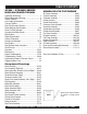
TABLE OF CONTENTS STOW — STR36SP SERIES RIDE-ON POWER TROWEL Proposition 65 Warning ............................................. 2 Silicosis/Respiratory Warnings .................................. 3 Table of Contents ...................................................... 4 Parts Ordering Procedures ....................................... 5 Training Checklist ...................................................... 6 Daily Pre-Operation Checklist ...................................
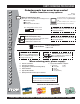
www.multiquip.com PARTS ORDERING PROCEDURES Ordering parts has never been easier! Choose from three easy options: Order via Internet (Dealers Only): Best Deal! Effective: January 1st, 2006 If you have an MQ Account, to obtain a Username and Password, E-mail us at: parts@multiquip. com. Order parts on-line using Multiquip’s SmartEquip website! N View Parts Diagrams N Order Parts N Print Specification Information To obtain an MQ Account, contact your District Sales Manager for more information.
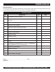
TRAINING CHECKLIST TRAINING CHECKLIST This checklist lists some of the minimum requirements for machine operation. Please feel free to make copies for daily use. Use this checklist when training a new operator or use as a review for more experienced operators. TRAINING CHECKLIST NO. DESCRIPTION 1 Read Operator’s Manual completely. 2 Machine layout, location of components, checking of engine and fluid levels. 3 Fuel system, refueling procedure. 4 Operation of spray and lights.
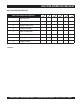
DAILY PRE-OPERATION CHECKLIST DAILY PRE-OPERATION CHECKLIST DAILY PRE-OPERATION CHECKLIST 1 Engine Oil Level. 2 Gearbox Fluid Level. 3 Radiator Coolant Level. 4 Condition of Blades. 5 Blade Pitch Operation. 6 Safety-Stop Switch Operation. 7 Steering Control Operation. 8 Condition of Belts. COMMENTS: STR36SP- SERIES • RIDE-ON POWER TROWEL — OPERATION AND PARTS MANUAL — REV.
STR36SP-SERIES — SAFETY MESSAGE ALERT SYMBOLS FOR YOUR SAFETY AND THE SAFETY OF OTHERS! Safety precautions should be followed at all times when operating this equipment. Failure to read, understand and comply with the Safety Messages and Operating Instructions could result in injury to yourself and others. This Operation Manual has been developed to provide instructions for the safe and efficient operation of the STR36SP -Series Ride-On Trowel.
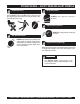
STR36SP-SERIES — SAFETY MESSAGE ALERT SYMBOLS Accidental Starting Accidental starts can cause severe injury or death. ALWAYS place the ON/OFF switch in the OFF position. Disconnect and ground spark plug lead and disconnect negative battery cable from battery before servicing. Respiratory Hazard ALWAYS wear approved respiratory protection. Sight and Hearing hazard ALWAYS wear approved eye and hearing protection.
STR36SP-SERIES — RULES FOR SAFE OPERATION RULES FOR SAFE OPERATION WARNING Failure to follow instructions in this manual may lead to serious injury or even death! This equipment is to be operated by trained and qualified personnel only! This equipment is for industrial use only. The following safety guidelines should always be used when operating the STR36SP-SERIES Ride-On Trowel.
STR36SP-SERIES — RULES FOR SAFE OPERATION ■ NEVER run engine without air filter. Severe engine damage may occur. Service air filter frequently to prevent carburetor malfunction. ■ NEVER place your feet or hands inside the guard rings while starting or operating this equipment. ■ AVOID wearing jewelry or loose fitting clothing that may snag on the controls or moving parts as this can cause a serious injury. ■ ALWAYS keep clear of rotating or moving parts while operating the trowel.
STR36SP-SERIES — RULES FOR SAFE OPERATION Transporting ■ ALWAYS shutdown engine before transporting. ■ Tighten fuel tank cap securely and close fuel petcock to prevent fuel from spilling. ■ Use chock-blocks at each wheel when parked to prevent trailer from rolling. ■ Use the trailer's swivel jack to adjust the trailer height to a level position while parked. ■ Drain fuel when transporting trowel for long distances or over bad roads. ■ Avoid sudden stops and starts.
STR36SP-SERIES — RULES FOR SAFE OPERATION Maintenance Safety Emergencies ■ ALWAYS shut down the engine and disconnect battery before performing service or maintenance functions. Contact with moving parts can cause serious injury. ■ ALWAYS know the location of the nearest fire extinguisher. ■ Securely support any trowel components that must be raised. ■ NEVER lubricate components or attempt service on a running trowel. ■ ALWAYS allow the trowel a proper amount of time to cool before servicing.
STR36SP-SERIES — OPERATION AND SAFETY DECALS Machine Safety Decals The STR36SP-SERIES Ride-On Power Trowel is equipped with a number of operation and safety decals. These decals are provided for operator safety and maintenance information. Should any of these decals become unreadable, replacements can be obtained from your dealer. WARNING To avoid injury, you MUST read and understand operator’s manual before using this machine. This machine to be operated by qualified personnel only.
STR36SP-SERIES— SPECIFICATIONS (TROWEL) C B A Figure 1. STR36SP-SERIES Dimensions Table 1. STR36 Specifications A–Length – in. (cm) 77.0 (195.6) B–Width – in. (cm) 39.0 (99) m C–Height – in. (c ) 46.75 (118.7) Weight – lbs. (kgs.) Operating 705 (320.5) Weight – lbs. (kgs.) Shipping 885 (402.27) Rotor – RPM (Dry Concrete) 180 Path Width – in. (cm) 75 (191) Hand/Arm Vibration 1 2.66 ft/s2 (m/s2) Whole Body Vibration TBD ft/s2 (m/s2) Sound Pressure (A-Weighted)2 TBD dB(A) NOTE: 1.
STR36SP-SERIES— SPECIFICATIONS (ENGINE) Table 2. STR36 Engine Specifications Model Honda GX670TAF Engine Type 4 Stroke, Overhead Valve 90 Degree V-Twin, gasoline engine. Piston Displacement 40.9 cu.in. (670 cc) Max. Output 24 bhp/3600 rpm (17.6 KW) Max. Torque 31.8 lbf-ft at 2500 rpm Cooling System Forced Air Engine Oil Capacity 1.69 qt. (1.6 liters) 2.01 qt. (1.9 liters w/oil filter replacement) Fuel Tank 5 gal.(19.23 liters) Gear Box Oil Capacity 69 oz. (2.
STR36SP-SERIES — GENERAL INFORMATION STR36SP Series Ride-On PowerTrowel Familarazation Gearboxes The STR36SP Series Ride-On Power Trowel is designed for the floating and finishing of concrete slabs. The STR36SP Series Ride-On Power Trowel uses two separate gearbox assemblies that are enclosed in rugged cast aluminum gear cases. Take a walk around your trowel.
STR36SP-SERIES — CONTROLS AND INDICATORS 1. Seat – Engine will neither start nor run unless operator is seated. 8. Choke Control Lever – In cold weather pull this lever to start engine. After engine warms push knob all the way in. 2. Steering Control Levers – Directs the unit forward, reverse, left, or right. 9. Fuel Gauge/Filler Cap – Indicates the amount of fuel in the fuel tank. Remove this cap to add fuel. 3.
STR36SP-SERIES — CONTROLS AND INDICATORS 17. Safety Stop Switch – Shuts down engine when seat is empty. 26. Spiders (Left/Right) – Consists of trowel arms, blades, wear plate, and thrust collar. 18. Light Assembly (Option) – Optional 12 volt halogen lights are available, two forward and one aft. 27. Document Box – Contains all product documentation. 28. Battery – Provides +12V DC power to the electrical system. 19. Lift Loops – Located on both sides of the main frame. Used to lift the trowel. 29.
STR36SP-SERIES — BASIC ENGINE 3 4 12 2 1 5 8 16 11 EN GIN EF UE 7 LO NL Y 10 13 6 9 15 14 Figure 4. Engine Controls and Components INITIAL SERVICING The engine (Figure 4) must be checked for proper lubrication and filled with fuel prior to operation. Refer to the manufacturer's engine manual for instructions & details of operation and servicing. The engine shown above is a HONDA engine. Operation for other types of engines may vary somewhat. 6.
STR36SP-SERIES — NEW MACHINE SETUP INSTRUCTIONS Trowel Pre-Set Up Instructions Seat Assembly The purpose of this section is to assist the user in setting up a NEW trowel. If your trowel is already assembled, (seat, handles, knobs and battery), this section can be skipped. The seat is not installed on the trowel for shipping purposes. To attach the seat perform the following: NOTE The new trowel cannot be put into service until the pre-setup installation instructions are completed.
STR36SP-SERIES — INITIAL START-UP The following section is intended as a basic guide to the ride-on trowel operation, and is not to be considered a complete guide to concrete finishing. It is strongly suggested that all operators (experienced and novice) read “Slabs on Grade ” published by the American Concrete Institute, Detroit Michigan. Table 3. Recommended Viscosity Grades DO NOT use your ride-on power trowel until this section is thoroughly understood.
STR36SP-SERIES — OPERATION EN GIN EF UE FUEL LO NL Y E F 5. When starting a cold engine, pull the choke knob, (Figure 9) out to the closed position. In warm weather or when the engine is warm, the unit can be started with choke halfway or completely open. Figure 7. Fuel Gauge Important Information Before You Start 1. This ride-on trowel is equipped with a safety "safety stop switch". This switch is located beneath the seat assembly.
STR36SP-SERIES — OPERATION Steering 5. Two control levers located in front of the operator’s seat provide directional control for the STR36SP SERIES Ride-On Power Trowel. Table 4 illustrates the various directional positions of the joysticks and their effect on the ride-on trowel. Try adjusting the pitch of the blades. This can be done with the ride-on trowel stopped or while the trowel is moving, whatever feels comfortable.
STR36SP-SERIES — MAINTENANCE Maintenance When performing any maintenance on the trowel or engine, follow all safety messages and rules for safe operation stated at the beginning of this manual. WARNING Air Cleaner (Daily) Thoroughly remove dirt and oil from the engine and control area. Clean or replace the air cleaner elements as necessary. Check and retighten all fasteners as necessary. 1. Release the four latch tabs (Figure 12) from the air cleaner cover, and remove the cover.
STR36SP-SERIES — MAINTENANCE CAUTION Operating the engine with a blocked grass screen, dirty or plugged cooling fins, and/or cooling shrouds removed, will cause engine damage due to overheating. Oil And Fuel Lines ■ Check the oil and fuel lines and connections regularly for leaks or damage. Repair or replace as necessary. ■ Replace the oil and fuel lines every two years to maintain the line's performance and flexibility. Changing Engine Oil (100 Hours) 1.
STR36SP-SERIES — MAINTENANCE Checking The Drive Belt 5 The drive belt needs to be replaced as soon as it starts to show signs of wear. Indications of excessive belt wear are fraying, squealing when in use, belts that emit smoke or a burning rubber smell when in use. Under normal operating conditions, a drive belt may last approximately 150 hours. If your trowel is not reaching this kind of life span for drive belt wear, check the drive belt for proper pulley alignment and spacing.
STR36SP-SERIES— MAINTENANCE 3. Insert the 3/4" X 1" X 3-1/4" block between the moveable face and the fixed face of the lower drive pulley. See Figure 18. This block will help keep the lower drive pulley faces open while installing the new drive belt. In the event of a drive belt failure, the spare (replacement) drive belt can be used for quick replacement at the job site to continue trowel operation. 1. If necessary, refer to Removing Drive Belt Instructions.
STR36SP-SERIES— MAINTENANCE 5 4 6 2 1 3 1 2 3 4 5 6 CV Joint Bolt (Remove 3 places) New Spare Drive Belt Bolt, Spare Drive Belt Carrier Spare Drive Belt Holder Left Side Gearbox Figure 20. Spare Drive Belt Replacement Spare Drive Belt Replacement It will be necessary to disconnect the CV-Joint from the left-side gearbox coupler. This means the removal of the three screws that secure the CVJoint to the gearbox. 3.
STR36SP-SERIES— MAINTENANCE Drive System Theory of Operation The STR36SP-SERIES Ride-On Power Trowel is equipped with a "Torque Converter" which supplies torque to both the left and right gearboxes. The function of the torque converter is to automatically deliver the correct amount of torque required by the trowel under all load conditions. This enables the trowel to deliver the necessary torque for float pan applications and the high rotor speeds required for burnishing concrete.
STR36SP-SERIES— MAINTENANCE How It Works (Figure 25) Condition A: Blade Pitch Engine Idling Drive Pulley: Small Driven Pulley: Large Belt: Loose and Stationary Condition B: Engine Accelerating Drive Pulley: Small But Increasing Sometimes it may be necessary to match blade pitch between the two sets of blades. There are some signs that this may be necessary. For example, the differences in pitch could cause a noticeable difference in finish quality between the two sets of blades.
STR36SP-SERIES — MAINTENANCE Trowel Arm adjustment Procedure NOTE Figure 29 illustrates the "correct alignment " for a spider plate (as shipped from the factory). The following procedure should be followed to adjust trowel arms when it becomes apparent that the trowel is finishing poorly or in need of routine maintenance. A level, clean area to test the trowel prior to and after adjustement is essential.
STR36SP-SERIES — MAINTENANCE Trowel Arm Removal Trowel Blade Removal 1. Each trowel arm is held in place at the spider plate by a hex head bolt (with zerk grease fitting). Remove the hex head bolt/zerk grease fitting from the spider plate. (Figure 31) 1. Remove the trowel blades from the trowel arm by removing the three hex head bolts (Figure 33) from the trowel arm. Set blades aside. 2. Remove the trowel arm from the spider plate. Figure 33.
STR36SP-SERIES — MAINTENANCE Checking Trowel Arm Straightness Trowel arms can be damaged by rough handling, (such as dropping the trowel on the pad), or by striking exposed plumbing, forms, or rebar while in operation. A bent trowel arm will not allow the trowel to operate in a smooth fluid rotation. If bent trowel arms are suspect, check for flatness as follows, refer to Figures 34 and 35. 3.
STR36SP-SERIES — MAINTENANCE 4. Use an allen wrench to tighten the locking bolts securing the trowel arm in place. 5. Adjust the bolt "distance" shown in Figure 36 to match one of the arms. The other arms will be adjusted to match this distance. 6. Loosen the locking nut on the trowel arm lever, then turn the trowel arm adjusting bolt until it barely touches (.010") the fixture adjusting bolt. 7. Once the correct adjustment is made, tighten the lock nut on the trowel arm to lock in place. Figure 37.
STR36SP-SERIES — MAINTENANCE Installing Pans Onto Finisher Blades These round discs sometimes referred to as "pans" attach to the spiders arms and allow early floating on wet concrete and easy movement from wet to dry areas. They are also very effective in embedding large aggregates and surface hardeners. 1. Lift trowel just enough to slide pan under blades. Lower finisher onto pan with blades (Item #1) adjacent to Z-Clips (Item #4). 2. Rotate blades into position under Z-Clips.
STR36SP-SERIES — TROUBLESHOOTING (ENGINE) TABLE 5. ENGINE TROUBLESHOOTING SYMPTOM Engine Cranks But Will Not Start Engine Starts But Will Not Continue Running POSSIBLE PROBLEM SOLUTION Fuel tank is empty. Fill fuel tank. Shut-off valve is closed. Open fuel shut-off valve. Fuel line has suction leak or is restricted. Fuel filter, or fuel tank cap vent is obstructed. Check fuel line condition and fuel line clamps. Ensure that fuel line is not kinked.
STR36SP-SERIES — TROUBLESHOOTING (ENGINE) TABLE 5 CONT.. ENGINE TROUBLESHOOTING SYMPTOM Engine Lacks Power POSSIBLE PROBLEM SOLUTION Air filter is obstructed. Replace air filter. Altitude causes 3% loss of horsepower per 1000 feet of altitude. If available, install high altitude jets in carburetor. Choke is par tially closed. Open choke. Faulty spark plugs or spark plug leads. Spark plug lead disconnected. Replace spark plugs or spark plug leads if faulty.
STR36SP-SERIES— TROUBLESHOOTING (TROWEL) TABLE 6. TROUBLESHOOTING SYMPTOM Engine running rough or not at all. POSSIBLE PROBLEM SOLUTION Safety Stop Switch malfunction? Make sure that the Safety Stop Switch is functioning when the operator is seated; replace switch if necessary. Fuel? Look at the fuel system. Make sure there is fuel being supplied to the engine. Check to ensure that the fuel filter is not clogged.
STR36SP-SERIES— TROUBLESHOOTING (TROWEL) TABLE 7. TROUBLESHOOTING (CONTINUED) SYMPTOM POSSIBLE PROBLEM SOLUTION Wiring? Check all electrical connections, including the master on/off switch and check to see if wiring is in good condition with no shor ts. Replace as necessary. Lights? Check to see if light bulbs are still good. Replace if broken. Lights (optional) not working. Retardant? Wiring? Check the tank to make sure retardant is present. Fill tank as necessary.
STR36SP-SERIES — NOTES STR36SP- SERIES • RIDE-ON POWER TROWEL — OPERATION AND PARTS MANUAL — REV.
STR36SP-SERIES — EXPLANATION OF CODES IN REMARKS COLUMN The following section explains the different symbols and remarks used in the Parts section of this manual. Use the help numbers found on the back page of the manual if there are any questions. NOTICE The contents and part numbers listed in the parts section are subject to change without notice. Multiquip does not guarantee the availability of the parts listed. SAMPLE PARTS LIST NO. 1 2% 2% 3 4 PART NO. PART NAME QTY. REMARKS 12345 BOLT...............
STR36SP-SERIES — SUGGESTED SPARE PARTS STR36SP-SERIES - HONDA GX670TAF 24 HP ENGINE 1 Unit Qty. P/N 4 4 4 4 2 2 20 20 20 4 4 4 20 20 20 4 4 1 20 1 1 1 1 20409 ............TROWEL ARM, LH 20408 ............TROWEL ARM, RH 1163 ..............LEVER TROWEL ARM (L.S.) 1555 ..............LEVER TROWEL ARM (R.S.) 10968 ............THRUST COLLAR KIT 12478 ............SPIDER KIT 0166A ............WASHER 1876 ..............JAM NUT 0164B ............SCREW 1157A ............BUSHING 1316 ..............SPRING (L.S.
STR36SP-SERIES — DECALS DECALS STR36SP-SERIES • RIDE-ON POWER TROWEL — OPERATION AND PARTS MANUAL — REV.
STR36SP-SERIES — DECALS DECALS NO. 1 1A 1B 1C 1D 1E 1F 1G 1H 2 3 4 5 6 7 8 9 10 11 12 13 14 15 16 18 PART NO. 11246 13118 TBD 2300 TBD 2634 1499 36099 2814 TBD 11092 35137 35168 20525 21455 36090 21600 PART NAME QTY. REMARKS DECAL SET, INTERNATIONAL STDS ................... 1 ..................
STR36SP-SERIES — PIVOT ASSY. (RIGHT/LEFT) PIVOT ASSY. (RIGHT/LEFT) STR36SP-SERIES • RIDE-ON POWER TROWEL — OPERATION AND PARTS MANUAL — REV.
STR36SP-SERIES — PIVOT ASSY. (RIGHT/LEFT) PIVOT ASSY. (RIGHT/LEFT) NO. 1 2 3 4 5 6 7 8 9 10 11 12 13 14 15 16 17 PART NO. 1023 0166A 2824 20040 10138 2044 2079 4196 20011 1394 11772 11773 2076 10133 10973 20004 1481 PART NAME QTY. REMARKS SCREW, HHC 3/8- 16 X 1-1/4 10 WASHER, LOCK, 3/8 MED. 18 BAR, 1” CONTROL PIVOT 2 ROCKER BLOCK, 1.
STR36SP-SERIES — STEERING HANDLES ASSY. (LEFT AND RIGHT) STEERING HANDLES ASSY, (LEFT AND RIGHT) STR36SP-SERIES • RIDE-ON POWER TROWEL — OPERATION AND PARTS MANUAL — REV.
STR36SP-SERIES — STEERING HANDLES ASSY. (LEFT AND RIGHT) STEERING HANDLES ASSY, (LEFT AND RIGHT) NO. 1 * 2 * 3 * 4 * 5 * 6 * 7 * 8 * 9 * 10 * 11 * 12 * 13 * 14 * 15 * 16 * 17 * 18 * 19 * 20 * 21 * 22 * 23 * 24 * 31 PART NO. 0189 2063 10130-1 2197 0424 11079-1 2196 2064 11498 2199 1284 10133 11080 2188 11513 2219 11497 1665 5228 1162A 0183 3550 11441 11303 7798-1 PART NAME QTY.
STR36SP-SERIES — STEERING CONTROL ASSY. (LEFT AND RIGHT) STEERING CONTROL ASSY., (LEFT AND RIGHT) STR36SP-SERIES • RIDE-ON POWER TROWEL — OPERATION AND PARTS MANUAL — REV.
STR36SP-SERIES — STEERING CONTROL ASSY. (LEFT AND RIGHT) STEERING CONTROL ASSY., (LEFT AND RIGHT) NO. 1 2 3 4 5 6 7 8 9 10 11 12 13 14 15 16 17 18 20 22 23 24 25 26 27 28 PART NO. 11146 11142 EM963105 10176 12625 0447 2064 0166A 1023 2199 2063 10133 11071-1 6014B 11275 11072 5228 1162A 10136 11138 11149 12408 11265 2219 12651-1 12650-1 PART NAME QTY. REMARKS NUT, HEX JAM 1/2-20 PLTD 2 ROD END, 1/2-20 MALE RH 2 SCREW, HHC 1/-13 X 2.......................................4.........
STR36SP-SERIES — GEARBOX ASSY. (RIGHT SIDE) GEARBOX ASSY. (RIGHT SIDE) STR36SP-SERIES • RIDE-ON POWER TROWEL — OPERATION AND PARTS MANUAL — REV.
STR36SP-SERIES — GEARBOX ASSY. (RIGHT SIDE) GEARBOX ASSY. (RIGHT SIDE) NO. PART NO. PART NAME QTY. REMARKS 1% 20065 SHAFT, GEARBOX INPUT W/FAN 1 2% 5031A SCREW, RHM 1/4- 20 X 1/2 4 3% 0948 WASHER, FLAT, 1/4 SAE 5 4% 12981 SHROUD, GB FIN COVER, RIGHT 1 5% 20353 GEAR BOX 1-1/8 SHAFT 1 6% 0121A FITTING, PLUG 3/8MP SQUARE HEAD 3 7% 10989 STUD, N10- 32 X 3/4 1 8% 12908 RIGHT HAND WORM 1 9% 1132 VENT, AIR 1 10% 12583 SPACER, X 11D X 1.
STR36SP-SERIES — GEARBOX ASSY. (LEFT SIDE) GEARBOX ASSY. (LEFT SIDE) STR36SP-SERIES • RIDE-ON POWER TROWEL — OPERATION AND PARTS MANUAL — REV.
STR36SP-SERIES — GEARBOX ASSY. (LEFT SIDE) GEARBOX ASSY. (LEFT SIDE) NO. PART NO.
STR36SP-SERIES — SINGLE PITCH HANDLE ASSY. (LEFT AND RIGHT) SINGLE PITCH HANDLE ASSY. (LEFT AND RIGHT) STR36SP-SERIES • RIDE-ON POWER TROWEL — OPERATION AND PARTS MANUAL — REV.
STR36SP-SERIES — SINGLE PITCH HANDLE ASSY. (LEFT AND RIGHT) SINGLE PITCH HANDLE ASSY. (LEFT AND RIGHT) NO 1#%+ 2#%+ 3#%+ 4#%+ 5#%+ 6#% 7#% 8#% 9#% 10#% 11#% 12#% 13# 14# 15# 16# 17# 18# 19# 20# 21# 22# 23# 24# 25# 26# 27# 28# 29# 30 PART NO 4403 3231 2575 1733 1616 2737 2621 1162A 4014 2332 2300 0185 1617 2170 1604 1111 2367 2169 10646 10382 10383 10723 2008 1116 10548 0202 0300B 5283 10512 11109-1 PART NAME QTY. REMARKS CRANK KNOB 2 SPACER 2 CRANK LEVER 2 HARDENED WASHER 2 SHOULDER BOLT 2 KNOB KIT ......
STR36SP-SERIES — DRIVE ASSY. DRIVE ASSY. STR36SP-SERIES • RIDE-ON POWER TROWEL — OPERATION AND PARTS MANUAL — REV.
STR36SP-SERIES — DRIVE ASSY. DRIVE ASSY. NO. 1 2% 3% 4% 5% 6% 7% 8% 9% 10% 11% 12% 13% 14% 15% 17% 18% 19% 20% 21% 22% 23% 24% 25% * 26% PART NO. 20077 20186 10909 0126 2090 1146 2037 2029 10337 20076 10136 10133 20137 20069 20116 12590 20056 2052 11108 1662 0243 0161C 2071 2259 2186 PART NAME QTY. REMARKS DRIVE ASSEMBLY ................................................. 1 ..........
STR36SP-SERIES — MUFFLER/BELT ASSY. MUFFLER/BELT ASSY. STR36SP-SERIES • RIDE-ON POWER TROWEL — OPERATION AND PARTS MANUAL — REV.
STR36SP-SERIES — MUFFLER/BELT ASSY. MUFFLER/BELT ASSY. NO. 1 2 3 4 5 6 7 8 9 10 11 12 13 14 15 16 17 18 19 20 PART NO. 20216 20336 0160C 2299 0300A 19470 2655 8239 5283 20138 12877 20265 2955 20264 15410ZJ4999AH 300518C 0131A 0181B 0948 2429 PART NAME ENGINE, HONDA 24 HP GX670 MUFFLER, 24 HONDA WASHER, LOCK 5/16 MEDIUM SCREW, HHC M8-1.25 X 16MM SCREW, HHC 5/16-18 X 2 WASHER, FLAT 5/16 USS HOUR METER RIVET, POP 1/8 DIA X .
STR36SP-SERIES — BELT GUARD ASSY. BELT GUARD ASSY. STR36SP-SERIES • RIDE-ON POWER TROWEL — OPERATION AND PARTS MANUAL — REV.
STR36SP-SERIES — BELT GUARD ASSY. BELT GUARD ASSY. NO. 1 2 3 PART NO. 20100 11819 11534 PART NAME BELT GUARD SCREW, HHC W/WASHER 1/4-20 X 3/4 NUT, U-TYPE 1/4-20 QTY. 1 4 4 REMARKS STR36SP- SERIES • RIDE-ON POWER TROWEL — OPERATION AND PARTS MANUAL — REV.
STR36SP-SERIES — SPIDER ASSY. (RIGHT) SPIDER ASSY. (RIGHT) STR36SP-SERIES • RIDE-ON POWER TROWEL — OPERATION AND PARTS MANUAL — REV.
STR36SP-SERIES — SPIDER ASSY. (RIGHT) SPIDER ASSY. (RIGHT) NO. 1% 2% 3% 4% 5 6 * 7 * 9 * 10 * 11 * 12 * 13 * 14 * 15 * 16 * 17 * 18 * 19 * 20 * 21 * 22 * 23 # * 24 * 25 26 27%+ 28 PART NO. 1154A 10793-1 12208 12778 1141 12097 1456 1157A 1317 1163 4164 20408 0202 0105 0161C 1162A 1322 1875 0164B 1876 0166A 11602 12477 20370-1 20415 1471 10968 PART NAME QTY. REMARKS PLATE, WEAR THRUST COLLAR 1 THRUST COLLAR W/ BUSHING ............................ 1 ..........
STR36SP-SERIES — SPIDER ASSY. (LEFT) SPIDER ASSY. (LEFT) STR36SP-SERIES • RIDE-ON POWER TROWEL — OPERATION AND PARTS MANUAL — REV.
STR36SP-SERIES — SPIDER ASSY. (LEFT) SPIDER ASSY. (LEFT) NO. 1% 2% 3% 4% 5 6 * 7 * 9 * 10 * 11 * 12 * 13 * 14+ 15+ 16+ 17 * 18 * 19 * 20 * 21 * 22 * 23# * 24 * 25 26 27%+ 28 PART NO. 1154A 10793-1 12208 12778 1141 12097 1456 1157A 1316 1555 4164 20409 0202 0105 0161C 1162A 1322 1875 0164B 1876 0166A 11602 12477 20369-1 20415 1471 10968 PART NAME QTY. REMARKS PLATE, WEAR THRUST COLLAR 1 THRUST COLLAR W/ BUSHING ............................ 1 ..........
STR36SP-SERIES — YOKE ASSY. YOKE ASSY. STR36SP-SERIES • RIDE-ON POWER TROWEL — OPERATION AND PARTS MANUAL — REV.
STR36SP-SERIES — YOKE ASSY. YOKE ASSY. NO. 1 2 3 4 5 6 PART NO. 9027 0683 10136 9028 1116 2008 PART NAME YOKE PIN, COTTER 3/32 X 3/4 WASHER, FLAT 3/8 SAE PIN, YOKE NUT, BRASS JAM 5/16-18 CABLE ASSEMBLY 25.63 QTY. 2 4 4 2 4 2 REMARKS STR36SP- SERIES • RIDE-ON POWER TROWEL — OPERATION AND PARTS MANUAL — REV.
STR36SP-SERIES — FOOT PEDALS/THROTTLE ASSY. FOOT PEDALS/THROTTLE ASSY. STR36SP-SERIES • RIDE-ON POWER TROWEL — OPERATION AND PARTS MANUAL — REV.
STR36SP-SERIES — FOOT PEDALS/THROTTLE ASSY. FOOT PEDALS/THROTTLE ASSY. NO. 1 2 3 4 5 6 7 8 9 10 11 12 13 14 15 16 17 18 19 20 21 22 23 24 25 26 PART NO.
STR36SP-SERIES — CONTROL PANEL ASSY. CONTROL PANEL ASSY. STR36SP-SERIES • RIDE-ON POWER TROWEL — OPERATION AND PARTS MANUAL — REV.
STR36SP-SERIES — CONTROL PANEL ASSY. CONTROL PANEL ASSY. NO. 1 2 3 4 5 6 8 9 10 11 12 13 14 15 16 17 18 19 20 21 PART NO. 2673 4682 20344 10019 20342 20343 2203 5065B 0730 10024 0948 19380 4538 20341 20340 8125 8381 11505 20339-1 20419 PART NAME CIRCUIT BREAKER, 30A, 12V SWITCH,TOGGLE ELECTRIC #9061 WIRE ASSEMBLY, 16 GA. X 5” NUT, NYLOC 10- 32 WIRE ASSEMBLY, 16 GA. X 7” WIRE ASSEMBLY, 16 GA.
STR36SP-SERIES — FRAME/FUEL ASSY. FRAME/FUEL ASSY. STR36SP-SERIES • RIDE-ON POWER TROWEL — OPERATION AND PARTS MANUAL — REV.
STR36SP-SERIES — FRAME/FUEL ASSY. FRAME/FUEL ASSY. NO. 1 2 3 4 5 6 7 8 9 10 11 12 13 14 15 16 17 18 19 20 PART NO. 12404 11418 19633 20795 19473 60013 20907 4514 0948 16910ZE8015 10024 20366 29057 12287 20943-1 11819 11534 0181B 4514 20014-1 PART NAME QTY. REMARKS TANK, FUEL FIVE GALLON 1 FUEL CAP/GAUGE (10.5) 1 BUSHING, RUBBER FUEL 1 VALVED, SCREENED DAPCO 1 CLAMP, WORM HOSE, #4 (1/4- 5/8) 3 HOSE, RUBBER FUEL 0.25 ID .......................... 2 ................. SOLD IN FT.
STR36SP-SERIES — BATTERY ASSY. BATTERY ASSY. STR36SP-SERIES • RIDE-ON POWER TROWEL — OPERATION AND PARTS MANUAL — REV.
STR36SP-SERIES — BATTERY ASSY. BATTERY ASSY. NO. 1 2 3 4 5 6 7 8 9 10 11 12 13 14 15 16 PART NO. 2509 10031 20356 20194 2449 2762 0131A 4671 0181B 0949 12022 12675 2623 3233 11505 5283 PART NAME WING NUT, PLATED WASHER, EXT SHKP 1/4 BRACKET BATTERY HOLD- DOWN BOLT, BATTERY HOLD DOWN BOX, BATTERY GR UI BOOT, TERMINAL SCREW, HHC 1/4- 20 X 3/4 BATTERY, GR. UI WET W /TAG WASHER,LOCK, 1/4 MEDIUM NUT, HEX FINISH 1/4- 20 CABLE, NEG 20- 1/2 CABLE, POS. BATTERY, 36’ SCREW, HHC 5/16- 18 X 1- 1/4 WASHER, FINDER 1.
STR36SP-SERIES — SEAT FRAME ASSY. SEAT FRAME ASSY. STR36SP-SERIES • RIDE-ON POWER TROWEL — OPERATION AND PARTS MANUAL — REV.
STR36SP-SERIES — SEAT FRAME ASSY. SEAT FRAME ASSY. NO. 1 2 3 4 5 6 7 8 9 10 11 12 13 14 15 16 17 18 19 20 21 PART NO. 21861 2421-1 0161C 1237 2889-1 11644 10237 8156 4001 11593 10133 0183 8081 10306 20346 10176 10019 12018 12017 12005 12020 PART NAME SEAT, MICHIGAN-ADJUSTABLE W/O ARMS SEAT PLATE WASHER, LOCK, 5/16 MEDIUM SCREW, SHC, 5/16- 18 X 7/8 NYLOC FRAME, SEAT SCREW, HHC, WASHER 10- 32 X 5/8 WASHER, EXT. SHKP, #10 SCREW, HHC 3/8- 16 X 2-1/2 WASHER, FLAT 3/8 PLTD STD.
HONDA GX-670 — AIR CLEANER ASSY. AIR CLEANER ASSY. STR36SP-SERIES • RIDE-ON POWER TROWEL — OPERATION AND PARTS MANUAL — REV.
HONDA GX-670 — AIR CLEANER ASSY. AIR CLEANER ASSY. NO. 1 2 3 4 5 6 8 9 10 11 12 PART NO. 17210ZJ1841 17218ZJ1840 17219ZJ1840 17220ZN1000 17229ZN1000 17230ZJ1840 17233ZJ1840 17234ZJ1840 17238ZJ4830 90003ZJ1840 957010602800 PART NAME ELEMENT COMP., AIR CLEANER FILTER, OUTER CLIP, AIR CLEANER HOUSING COMP., AIR CLEANER SEAL, AIR CLEANER HOUSING COVER ASSEMBLY, AIR CLEANER SEAL, AIR CLEANER COVER PLATE, AIR CLEANER SETTING COLLAR A, AIR CLEANER BOLT, SPECIAL 5MM BOLT, FLANGE 6 X 28 QTY.
HONDA GX-670 — CAMSHAFT ASSY. CAMSHAFT ASSY. STR36SP-SERIES • RIDE-ON POWER TROWEL — OPERATION AND PARTS MANUAL — REV.
HONDA GX-670 — CAMSHAFT ASSY. CAMSHAFT ASSY. NO. 1 2 3 4 5 6% 7% 8 9 10 11 12 * 13 * 14 15 16 17 18 19 20 21 22 23 * 24 25 * 26% 27 PART NO. 12209ZE8003 14100ZJ1842 14410ZJ1840 14431ZE2010 14451ZE1013 14568ZJ1841 14576ZJ1840 14711ZE3000 14721ZE3000 14730ZJ1840 14751ZE2003 14760ZJ1840 14764ZJ1840 14771ZE2000 14773ZE2000 14775ZE2010 14781ZE2000 14791ZE2010 90005895000 90012ZE0010 90206ZE1000 90446357000 90602ZE1000 9430108120 9410106800 9430560282 957010602500 PART NAME QTY.
HONDA GX-670 — CARBURETOR ASSY. CARBURETOR ASSY. STR36SP-SERIES • RIDE-ON POWER TROWEL — OPERATION AND PARTS MANUAL — REV.
HONDA GX-670 — CARBURETOR ASSY. CARBURETOR ASSY. NO. 1 2 3 + * 4 * 5 * 6 * 7 + * 8 * 9 * 10 11 * 12 * 13 14 * 15 16 17 18 19% 20 21 22% 23 24 25 26 27 28 29 30 * 30 31 * 31 31 31 32 PART NO.
HONDA GX-670 — CONTROL ASSY. CONTROL (2) ASSY. STR36SP-SERIES • RIDE-ON POWER TROWEL — OPERATION AND PARTS MANUAL — REV.
HONDA GX-670 — CONTROL ASSY. CONTROL (2) ASSY. NO. 1 2 3 4 5 6 7 8 * 9 * 10 * 11 * 12 13 14 15 16 17 18 19 20 * 21 22 23 24 PART NO. 16263883W10 16500ZJ1850 16534ZN1000 16551ZJ1840 16555ZN1000 16561ZN1800 16562ZN1000 16570ZJ1850 16574883300 16575ZJ1850 16576883300 16584883300 16611ZN1000 16628ZJ1850 17850ZJ1850 17951921030 17957ZV4000 90014952000 90015ZE3790 90114SA0000 92301050250A 93500050250A 9405006000 9425110000 PART NAME QTY. REMARKS JOINT, ROD 1 CONTROL ASSEMBLY ................................ 1 .
HONDA GX-670 — CONTROL BOX ASSY. CONTROL BOX ASSY. STR36SP-SERIES • RIDE-ON POWER TROWEL — OPERATION AND PARTS MANUAL — REV.
HONDA GX-670 — CONTROL BOX ASSY. CONTROL BOX ASSY. NO. 1 * 2 * 3 4 5 6 7 * 8 9 * 10 * 11 % * 12 13 * 14 * 15 16 17 18 19 20 * 21 * 22 23 24 % * PART NO. 31612ZE2003 31614ZE2003 31620ZG5003 32103759000 32105ZJ1800 32340ZJ1841 32345ZJ1811 32349ZJ1840 32902892003 35100ZJ1841 35111880003 36103ZE1000 87529ZE2860 90380MA6010 32171GJ1003 90676SA8003 91408ZJ1810 91504750003 93500040120H 94001040800S 9411104800 957010601000 957010601200 9820032500 PART NAME QTY.
HONDA GX-670 — CRANKCASE COVER ASSY. CRANKCASE COVER ASSY. STR36SP-SERIES • RIDE-ON POWER TROWEL — OPERATION AND PARTS MANUAL — REV.
HONDA GX-670 — CRANKCASE COVER ASSY. CRANKCASE COVER ASSY. NO. 1 2 4 5 6 7 8 9 10 11 12 * 13 % * 14 % * 15 % * 16 * 17 18 19 * 20 * 21 * 22 23 * 24 25 26 27 28 PART NO. 11300ZJ1840 11381ZJ1840 15124ZJ1000 15124ZJ1003 15232ZJ1000 15348ZJ1840 15410ZJ4999AH 15411ZN1000 15427ZJ1000 15655ZJ1860 16510ZJ1840 16511ZJ1840 16512ZJ1840 16513ZE2000 16531ZE2000 90015883000 90018PN3000 90473147000 90602ZE1000 91202ZJ1841 91320MJ6003 9410106800 9430108140 957010602000 957010805000 9621112000 966000601600 PART NAME QTY.
HONDA GX-670 — CRANKSHAFT ASSY. CRANKSHAFT ASSY. STR36SP-SERIES • RIDE-ON POWER TROWEL — OPERATION AND PARTS MANUAL — REV.
HONDA GX-670 — CRANKSHAFT ASSY. CRANKSHAFT ASSY. NO. 1 3 PART NO. 13310ZN1000 90401ZJ1000 PART NAME CRANKSHAFT COMP., T-TYPE WASHER, CRANKSHAFT THRUST QTY. 1 1 REMARKS STR36SP- SERIES • RIDE-ON POWER TROWEL — OPERATION AND PARTS MANUAL — REV.
HONDA GX-670 — CYLINDER BARREL ASSY. CYLINDER BARRELASSY. STR36SP-SERIES • RIDE-ON POWER TROWEL — OPERATION AND PARTS MANUAL — REV.
HONDA GX-670 — CYLINDER BARREL ASSY. CYLINDER BARREL ASSY. NO. 1 2 3 4 5 6 8 10 11 12 13 14 * 15 16 * 17 * 18 20 21 23 24 26 PART NO. 12000ZN1010 12356ZJ1000 12358ZJ1000 12372ZE2300 15558ZJ010AH 16541ZJ1840 31511ZJ1000 37240ZG3E01 90002ZG5004 90029888000 90031ZE1000 91001ZJ1841 91002ZJ1841 91201ZE9003 91201ZJ1841 91302MB6830 9280014000 9410208800 9410914000 9425108000 961406003010 PART NAME QTY. REMARKS CYLINDER ASSEMBLY ........................................ 1 ..........
HONDA GX-670 — CYLINDER HEAD ASSY. CYLINDER HEAD ASSY. STR36SP-SERIES • RIDE-ON POWER TROWEL — OPERATION AND PARTS MANUAL — REV.
HONDA GX-670 — CYLINDER HEAD ASSY. CYLINDER HEAD ASSY. NO. 1 2 % * 3 % * 4 5 % * 6 7 8 9 10 11 12 13 14 15 16 17 18 19 20 21 22 23 24 25 26 PART NO. 11911ZJ1840 12204ZE2306 12205ZJ1405 12210ZJ1840 12216ZE2300 12220ZJ1840 12251ZJ1841 12311ZJ1840 12314ZJ1840 12391ZE2020 15611MB0000 15625ZJ1840 17101ZN1000 17151ZJ1841 18333ZE3800 19682ZJ1840 90011ZJ1841 90014ZE2000 90014952000 90018ZJ1840 90441ZE2010 9405008000 9430112200 957010802000 957011008000 9807952876 PART NAME QTY.
HONDA GX-670 — FAN COVER ASSY. FAN COVER ASSY. STR36SP-SERIES • RIDE-ON POWER TROWEL — OPERATION AND PARTS MANUAL — REV.
HONDA GX-670 — FAN COVER ASSY. FAN COVER ASSY. NO. 2 3 4 5 6 7 8 10 11 12 13 14 15 17 18 PART NO. 16715ZJ1850 19611ZJ1840ZA 19612ZJ1840 19614ZJ1840 19631ZJ1840 19632ZN1000 33713GC2000 80101310000 90013883000 90018ZE1000 90042ZJ1840 90313ZJ1840 9391325580 9405006000 957010600800 PART NAME COVER, FUEL PUMP, MANUAL CONTROL COVER, FAN *NH1* (BLACK) PLATE, RIGHT SIDE PLATE, LEFT SIDE SHROUD, RIGHT SHROUD, LEFT COLLAR B, TAIL LIGHT RUBBER, RR.
HONDA GX-670 — FLYWHEEL ASSY. FLY WHEEL ASSY. STR36SP-SERIES • RIDE-ON POWER TROWEL — OPERATION AND PARTS MANUAL — REV.
HONDA GX-670 — FLYWHEEL ASSY. FLY WHEEL ASSY. NO. 1 2 3 4 5 6 7 8 9 10 PART NO. 19511ZJ1000 19513ZJ1000 28452ZJ1811 28454ZJ1801 31110ZJ1840 90201ZG3000 90401ZG3000 90741ZE2000 957010601200 957010801600 PART NAME FAN, COOLING PLATE, COOLING FAN SETTING GRID, SCREEN P.T.O. (OPTIONAL) HOLDER, SCREEN GRID, OPTIONAL FLY WHEEL COMP. NUT, FLANGE 20MM WASHER 20MM KEY, SPECIAL WOODRUFF 25 X 18 BOLT, FLANGE 6 X 12 (OPTIONAL) BOLT, FLANGE 8 X 16 QTY.
HONDA GX-670 — FUEL PUMP ASSY. FUEL PUMP ASSY. STR36SP-SERIES • RIDE-ON POWER TROWEL — OPERATION AND PARTS MANUAL — REV.
HONDA GX-670 — FUEL PUMP ASSY. FUEL PUMP ASSY. NO. 1 2 3 4 5 6 7 8 9 10 11 12 13 14 15 PART NO. 16700ZL8003 16711ZJ1840 16851ZN1000 16852ZJ1840 16882ZJ1840 16910ZE8015 19111MF5000 90014952000 90517SA0003 91601ZJ1840 938940601600 9500202080 9500202100 9500250000 9500270000 PART NAME PUMP ASSEMBLY, FUEL STAY, FUEL PUMP TUBE, FUEL TUBE B, FUEL TUBE, DIAPHRAGM FILTER COMP.
HONDA GX-670 — IGNITION COIL ASSY. IGNITION COIL ASSY. STR36SP-SERIES • RIDE-ON POWER TROWEL — OPERATION AND PARTS MANUAL — REV.
HONDA GX-670 — IGNITION COIL ASSY. IGNITION COIL ASSY. NO. 1 2 3 4 5 6 7 8 * 9 10 PART NO. 30500ZJ1841 30518ZJ1000 30550ZJ1841 30700ZJ1841 31630ZJ1801 31740ZJ1841 32763PA0000 63312ZA7000 90031ZE1000 957010600800 PART NAME QTY. REMARKS COIL ASSEMBLY R. IGNITION 1 GROMMET, IGNITION WIRE 2 COIL ASSEMBLY, L.. IGNITION 1 CAP ASSEMBLY, NOISE SUPPRESSOR 2 COIL ASSEMBLY, CHARGE 12V/20A 1 DIODE ASSEMBLY, ENGINE STOP ..................... 1 ..........
HONDA GX-670 — LABELS ASSY. LABELS ASSY. STR36SP-SERIES • RIDE-ON POWER TROWEL — OPERATION AND PARTS MANUAL — REV.
HONDA GX-670 — LABELS ASSY. LABELS ASSY. NO. 1 2 5 PART NO. 87101ZN1000 87152ZN1000 87532ZJ1840 PART NAME MARK, EMBLEM LABEL, SPECIFICATION G X 670 MARK, THROTTLE INDICATION QTY. 1 1 1 REMARKS STR36SP- SERIES • RIDE-ON POWER TROWEL — OPERATION AND PARTS MANUAL — REV.
HONDA GX-670 — OIL COOLER ASSY. OIL COOLER ASSY. STR36SP-SERIES • RIDE-ON POWER TROWEL — OPERATION AND PARTS MANUAL — REV.
HONDA GX-670 — OIL COOLER ASSY. OIL COOLER ASSY. NO. 1 * 2 3 * 4 5 6 7 8 * 9 10 11 12 PART NO. 11513MN5300 15605ZN1000 15610ZN1000 15613ZN1000 15614ZN1003 15616ZN1003 15676ZN1000 19051KA3830 19314PH6000 91314ME5003 957010602200 90014952000 PART NAME QTY. REMARKS COLLAR 12MM 2 COOLER ASSEMBLY, OIL .................................... 1 .......... INCLUDES ITEMS W/ * COOLER COMP., OIL 1 GRILLE, OIL COOLER 1 HOSE A, OIL 1 HOSE B, OIL 1 STAY, OIL COOLER 1 RUBBER, RADIATOR MOUNTING 2 CLAMP, HOSE D13.
HONDA GX-670 — PISTON + CONNECTING ROD ASSY. PISTON + CONNECTING ROD ASSY. STR36SP-SERIES • RIDE-ON POWER TROWEL — OPERATION AND PARTS MANUAL — REV.
HONDA GX-670 — PISTON + CONNECTING ROD ASSY. PISTON + CONNECTING ROD ASSY. NO. 1 1 1 1 2 2 2 2 3 4 6 7 PART NO. 13010ZJ1841 13011ZJ1841 13012ZJ1841 13013ZJ1841 13101ZN1000 13102ZN1000 13103ZN1000 13104ZN1000 13111ZJ1840 13200ZN1003 90001ZN1000 9460118000 PART NAME RING SET, PISTON STD. RING SET, PISTON OS 0.25 (OPTIONAL) RING SET, PISTON OS 0.50 (OPTIONAL) RING SET, PISTON 0.75 (OPTIONAL) PISTON STD. PISTON OS 0.25 (OPOTIONAL) PISTON OS 0.50 (OPTIONAL) PISTON 0.
HONDA GX-670 — STARTER MOTOR ASSY. STARTER MOTOR ASSY. STR36SP-SERIES • RIDE-ON POWER TROWEL — OPERATION AND PARTS MANUAL — REV.
HONDA GX-670 — STARTER MOTOR ASSY. STARTER MOTOR ASSY. NO. 1 * 2 * 3 4 * 5 * 6 * 7 * 8 * 9 * 10 * 11 * 12 * 13 * 14 * 15 * 16 * 17 * 18 * 19 * 20 * 21 22 PART NO. 30201PH9004 30202PZ1003 31200ZJ1841 31203PH9004 31204ZJ1H01 31206ZG4801 31207ZJ1H01 31211PH9004 31212PH9004 31213P64N01 31214PH9004 31216ZJ1H01 31220PH9004 31223PA0006 31231PH9004 31233PH9004 31234ZJ1H01 91002ZG4801 94001080000S 9411108000 9430110120 957010811000 PART NAME QTY.
TERMS AND CONDITIONS OF SALE — PARTS Terms And Conditions Of Sale STOW Construction Equipment PAYMENT TERMS Terms of payment for unit sales are 2% 15 days net 30 days from date of invoice unless otherwise specifically stated on our invoice. Parts invoices have terms of net 10 days. Minimum parts billing is $15.00 net. Applicable discounts will be computed on merchandise value only. Late charges will be assessed at prevailing rates.
STR36SP-SERIES—NOTES STR36SP- SERIES • RIDE-ON POWER TROWEL — OPERATION AND PARTS MANUAL — REV.
OPERATION AND PARTS MANUAL HERE’S HOW TO GET HELP PLEASE HAVE THE MODEL AND SERIAL NUMBER ON-HAND WHEN CALLING UNITED STATES Multiquip Corporate Office 18910 Wilmington Ave. Carson, CA 90746 Contact: mq@multiquip.com MQ Parts Department Tel.