OPERATION AND PARTS MANUAL MODEL MS-70 PLASTER AND MORTAR MIXER (GASOLINE ENGINE/ELECTRIC MOTOR) Revision #3 (03/26/10) THIS MANUAL MUST ACCOMPANY THE EQUIPMENT AT ALL TIMES.
Engine exhaust and some of its constituents, and some dust created by power sanding, sawing, grinding, drillingandotherconstructionactivities contains chemicals known to the State of California to cause cancer, birth defects and other reproductive harm. Some examples of these chemicals are: Leadfromlead-basedpaints. Crystallinesilicafrombricks. Cementandothermasonryproducts. Arsenicandchromiumfromchemically treatedlumber.
HERE'S HOW TO GET HELP PLEASE HAVE THE MODEL AND SERIAL NUMBER ON-HAND WHEN CALLING STOW MAIN OFFICE Post Office Box 6254 Carson, Ca 90749 Email: stow@multiquip.com Internet: www.stowmfg.com PARTS DEPARTMENT 800-427-1244 310-537-3700 SERVICE DEPARTMENT 800-421-1244 310-537-3700 TECHNICAL ASSISTANCE 800-478-1244 WARRANTY DEPARTMENT 800-421-1244, EXT. 279 310-537-3700, EXT.
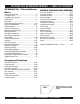
STOW MS-70 PLASTER/MORTAR MIXER — TABLE OF CONTENTS STOW MS-70 — Plaster/Mortar Mixer Here's How To Get Help .................................................. 3 Table Of Contents ........................................................... 4 Parts Ordering Procedures ............................................. 5 Specifications ................................................................. 6 Dimensions .....................................................................
STOW MS-70 MIXER — PARTS ORDERING PROCEDURES When ordering parts, please supply the following information: ❒ ❒ ❒ ❒ ❒ ❒ ❒ Dealer account number Dealer name and address Shipping address (if different than billing address) Return fax number Applicable model number Quantity, part number and description of each part Specify preferred method of shipment: ✓ FedEx or UPS Ground Note: Unless otherwise indicated by customer, all ✓ FedEx or UPS Second Day or Third Day orders are treated as “Standard Orders”, and will
STOW MS-70 PLASTER/MORTAR MIXER — SPECIFICATIONS TABLE 1. MIXER SPECIFICATIONS Capacity 7.0 cu. ft (198 liters) Bag Capacity 1-1/2 to 2-1/2 bags Weight 788 lbs. (357 kg.) Height W/Dump Handle 73 in. (185 cm.) Discharge Height 21 in. (53 cm.) Drive V-Belt/Gear Dump Action Manual Table 2. Specifications (Engine & Electric Motor) Model Type Engine/Electric Motor 1.5 HP, 115/230, Single Phase Electric Motor N/A Displacement 14.81 cc N/A 8.0 H.P./3600 R.P.M. 1.5 H.P./1725 RPM Approx. 1.
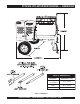
STOW MS-70 PLASTER/MORTAR MIXER — DIMENSIONS TABLE 3. DIMENSIONS Description Dimensions in. (cm) Length (w/ Tow Bar) 67 in. (170 cm) Width 50 in. (127 cm) Height 56 in. (142 cm) Figure 1. Dimensions STOW MS-70 MIXER — OPERATION MANUAL — REV.
STOW MS-70 MIXER — SAFETY MESSAGE ALERT SYMBOLS FOR YOUR SAFETY AND THE SAFETY OF OTHERS! HAZARD SYMBOLS Safety precautions should be followed at all times when operating this equipment. Failure to read and understand the Safety Messages and Operating Instructions could result in injury to yourself and others.
STOW MS-70 MIXER — SAFETY MESSAGE ALERT SYMBOLS CAUTION Rotating Parts Hazards NEVER operate equipment with covers, or guards removed. Keep fingers, hands, hair and clothing away from all moving parts to prevent injury. CAUTION CAUTION Equipment Damage Hazards Other important messages are provided throughout this manual to help prevent damage to your light tower, other property, or the surrounding environment.
STOW MS-70 PLASTER/MORTAR MIXER — RULES FOR SAFE OPERATION DANGER Read this manual! Failure to follow instructions in this manual may lead to serious injury or even death! This equipment is to be operated by trained and qualified personnel only! This equipment is for industrial use only. The following safety guidelines should always be used when operating the STOW MS-70 mortar and plaster mixer: GENERAL SAFETY ■ DO NOT operate or service this equipment before reading this entire manual.
STOW MS-70 PLASTER/MORTAR MIXER — RULES FOR SAFE OPERATION ■ ALWAYS stop the engine before servicing, adding fuel and oil. ■ NEVER run engine without air filter. Severe engine may occur. ■ ALWAYS service air cleaner frequently to prevent carburetor malfunction. ■ ALWAYS check the machine for loosened threads or bolts before starting. ■ ALWAYS be sure the operator is familiar with proper safety precautions and operations techniques before using mixer.
STOW MS-70 PLASTER/MORTAR MIXER — TOWING GUIDELINES Towing Safety Precautions Regularly Inspect Towing Components To reduce the possibility of an accident while transporting the mixer on public roads, always make sure that the mixer towing components and the towing vehicle are in good operating condition and both units are mechanically sound. CAUTION ■ ALWAYS make sure that the fuel valve lever is in the OFF position (gasoline models only). ■ Check wheel mounting lug nuts with a torque wrench.
STOW MS-70 PLASTER/MORTAR MIXER — SAFETY CHAIN CONNECTION CAUTION Always Tow with a Safety Chain NEVER! tow the mixer with the safety chain removed. The safety chain is intended to prevent complete separation of the mixer from the towing vehicle in the event of a tow bar failure. Reference Figure 2 for the installation of the safety chain. Tow Bar to Mixer Connection 1. Insert the tow bar through the round opening at the bottom of the mixer stand.
MS-70 PLASTER/MORTAR MIXER — OPERATION AND SAFETY DECALS Machine Safety Decals The STOW MS-70 mortar and plaster mixer is equipped with a number of safety decals. These decals are provided for operator safety and maintenance information. Figure 4 below illustrates these decals as they appear on the machine. Should any of these decals become unreadable, replacements can be obtained from your dealer. Figure 4. Mixer Operation and Safety Decals PAGE 14 — STOW MS-70 MIXER — OPERATION MANUAL — REV.
STOW MS-70 PLASTER/MORTAR MIXER — GENERAL INFORMATION Application The STOW MS-70 series mixers (drum capacity of 7.0 cu. ft./198 liters) are shipped completely assembled and have been factory tested and are ready for use. This mixer is only intended for the production of plaster and mortar. The mixer must be used for its intended purpose and is not suitable for the mixing of flammable or explosive substances. The mixer must not be used in an explosive atmosphere.
STOW MS-70 PLASTER/MORTAR MIXER — BASIC MIXER COMPONENTS 8. Mixing Paddles — Used in the mixing of material. This unit uses four different types of paddles to provide a fast uniform mix. 9. Bag Cutter— This feature allows compound mixing bags to be opened easily, therefore allowing the contents of the bag to fall directly into the mixing drum. 10. Safety Grill — Provided for operator safety. This safety grill is designed to keep hands and solid objects out of the mixing drum when in use.
STOW MS-70 PLASTER/MORTAR MIXER — BASIC ENGINE COMPONENTS Figure 6. Engine Controls and Components INITIAL SERVICING 5. The engine (Figure 6) must be checked for proper lubrication and filled with fuel prior to operation. Refer to the manufacturers Engine manual for instructions & details of operation and servicing. Fuel Valve Lever – OPEN to let fuel flow, CLOSE to stop the flow of fuel. 6. Choke Lever – Used in the starting of a cold engine, or in cold weather conditions.
STOW MS-70 PLASTER/MORTAR MIXER — ELECTRIC MOTOR Electric Motor TABLE 5. ELECTRIC MOTOR WIRING INFORMATION For maintenance care and operation of the electric motor, refer to your electric motor instruction booklet furnished with the motor. Protect the electric motor from dust as much as possible and keep ventilating openings clean. Electric Motor Safety DO NOT spray water at any time on the electric motor.
STOW MS-70 PLASTER/MORTAR MIXER — ELECTRIC MOTOR The motor supplied is wired for 115 VAC grounded operation. Make certain that the correct size grounded (3-wires) extension cord is used. See Table 6. Motors can burn out when the line voltage falls 10% below the voltage rating of the motor. Failure to use proper voltage will cause the motor to overheat and actuate the overload switch. TABLE 6. RECOMMENDED EXTENSION CORD SIZES Model Motor Voltage WM-70 1.5 HP (Electric) 50 ft. 75 ft. (15.24 m) (22.
STOW MS-70 — PADDLE BLADE ADJUSTMENT (STEEL DRUM) Adjust paddles as shown in Figure 8. Figure 8. Paddle Blade Adjustment, Steel Drum PAGE 20 — STOW MS-70 MIXER — OPERATION MANUAL — REV.
STOW MS-70 PLASTER/MORTAR MIXER — INSPECTION Before Starting 1. Read all safety instructions at the beginning of manual. 2. Clean the mixer, removing dirt and dust, particularly the engine cooling air inlet, carburetor and air cleaner. 3. Check the air filter for dirt and dust. If air filter is dirty, replace air filter with a new one as required. 4. Check carburetor for external dirt and dust. Clean with dry compressed air. 5. Check fastening nuts and bolts for tightness. CAUTION 3.
STOW MS-70 PLASTER/MORTAR MIXER — INSPECTION Fuel Check Explosive Fuel Hazard If your mixer has a gasoline engine, determine if the engine fuel is low. If fuel is low, remove the fuel filler cap and fill with unleaded gasoline. Motor fuels are highly flammable and can be dangerous if mishandled. DO NOT smoke while refueling. DO NOT attempt to refuel the mixer if the engine is hot! or running. DANGER V-belt Check A worn or damaged V-belt can adversely affect the performance of the mixer.
STOW MS-70 PLASTER/MORTAR MIXER — START-UP PROCEDURES This section is intended to assist the operator with the initial start-up of the STOW MS-70H (gasoline engine) or STOW MS-70E (electric motor) mixer. It is extremely important that this section be read carefully before attempting to use the mixer in the field. 2. To start a cold engine, move the choke lever (Figure 12) to the CLOSED position. DO NOT use your mixer until this section is thoroughly understood.
MS-70 PLASTER/MORTAR MIXER — START-UP PROCEDURES 4. Turn the engine switch (Figure 14) to the ON position. CAUTION Preventing Drum Tipping Make certain the drum lock pin (Figures 17 and 18) is placed to the RIGHT (when viewing the mixer from the towpole end) of the drum stop block which is welded to the front side of the drum. Also make sure lock pin is fully engaged (locked). This will prevent the drum from tipping. Figure 14. Engine ON/OFF Switch 5.
STOW MS-70 PLASTER/MORTAR MIXER — OPERATION/SHUT-DOWN 8. Place the belt slip lever (Figure 20) in the mix position. This will tilt the engine placing tension on the V-belts enabling the shaft to rotate. WARNING Dump Handle Safety Be sure to stand clear of the dump handle (Figure 22) when the mixer is operational. Any binding of material between the mixer blades and the drum will cause the drum handle to move to the discharge position and could cause bodily harm. Figure 20.
STOW MS-70 PLASTER/MORTAR MIXER — MAINTENANCE (ENGINE) Use Table 8 as a general maintenance guideline when servicing your engine. For more detail engine maintenance information, refer to the engine owner's manual supplied with your engine. Table 8. Engine Maintenance Schedule DESCRIPTION (3) OPERATION BEFORE CHECK X FIRST EVERY MONTH 3 MONTHS OR OR 10 HRS. 25 HRS. EVERY 6 MONTHS OR 50 HRS. EVERY YEAR OR 100 HRS. EVERY 2 YEARS OR 200 HRS.
STOW MS-70 PLASTER/MORTAR MIXER — MAINTENANCE (ENGINE) Maintenance Perform the scheduled maintenance procedures as defined by Table 8 and below: DAILY ■ Thoroughly remove dirt and oil from the engine and control area. Clean or replace the air cleaner elements as necessary. Check and retighten all fasteners as necessary. Check the gearbox for oil leaks. Repair or replace as needed. WEEKLY ■ Remove the fuel filter cap and clean the inside of the fuel tank.
STOW MS-70 PLASTER/MORTAR MIXER — MAINTENANCE (MIXER) Ball Socket and Clamp Face Maintenance 1. 2. 3. If the towing vechicle is equipped with a ball socket, smear socket periodically with multi-purpose grease. This will keep the ball socket well lubricated. Periodically oil pivot points and clamp face surfaces of coupler with SAE 30 WT. motor oil. When parking or storing your mixer. Keep the coupler off the ground so dirt will not build up in the ball socket.
STOW MS-70 PLASTER/MORTAR MIXER — MAINTENANCE (MIXER) 2. Fill the wheel hub (Figure 28) with grease to the inside diameter of the outer races and also fill the hub grease cap. Reassemble the hub and mount the wheel. Then tighten the adjusting nut, at the same time turn the wheel in both directions, until there is a slight bind to be sure all the bearing surfaces are in contact.
STOW MS-70 PLASTER/MORTAR MIXER — MAINTENANCE (MIXER) Grease Fittings (Zerk) Maintenance (Electric Motor) 1. 2. There are two grease (Figure 33) fittings at each end of the electric motor that will require lubrication. Lubricate these fittings about every 16 months. Use Poleyrex EM (Exxon Mobil) or equalivant lubricant. Clean grease fitting, apply grease gun to fitting (1/2 shot). Remember too much grease or injecting grease too quickly can cause premature bearing failure.
STOW MS-70 PLASTER/MORTAR MIXER — MAINTENANCE (MIXER) Lug Nut Torque Requirements It is extremely important to apply and maintain proper wheel mounting torque. Be sure to use only the fasteners matched to the cone angle of the wheel. Proper procedure for attachment of the wheels is as follows: 3. After first road use, retorque all lug nuts in sequence. Check all wheel lug nuts periodically. 1. Start all wheel lug nuts by hand. 2. Torque all lug nuts in sequence. See Figure 34.
STOW MS-70 PLASTER/MORTAR MIXER — MAINTENANCE (MIXER) Suspension Keep Hands Clear of Drum! When rotating the mixing drum from the dump position to the upright position, keep hands clear of safety grate. The possibility exists of hands or fingers being crushed (Figure 37). WARNING The rigid type axle and associated hardware (Figure 35) should be periodically inspected for signs of excessive wear, elongation of bolt holes, and loosening of fasteners. Replace all damaged parts immediately. Figure 35.
STOW MS-70 PLASTER/MORTAR MIXER — TROUBLESHOOTING (ENGINE) Practically all breakdowns can be prevented by proper handling and maintenance inspections, but in the event of a breakdown, please take a remedial action following the diagnosis based on the Engine, Mixer and Electric Motor Troubleshooting (Tables 11, 12 and 13) information shown below and on the proceeding pages. If the problem cannot be remedied, please leave the unit just as it is and consult or company's service department. TABLE 11.
STOW MS-70 PLASTER/MORTAR MIXER — TROUBLESHOOTING (ENGINE) TABLE 11. ENGINE TROUBLESHOOTING (CONTINUED) SYMPTOM POSSIBLE PROBLEM Insufficient power output "compression" and overheats Burns to much fuel Exhaust color is continiously "WHITE" Exhaust color is continiously "BLACK" SOLUTION Malfunction in cooling fan? Check or replace cooling fan. Air in-take filter clogged? Clean or replace air in-take filter. Over accumulation of exhaust products? Clean and check valves.
STOW MS-70 — TROUBLESHOOTING (MIXER/ELECTRIC MOTOR) TABLE 12. MIXER TROUBLESHOOTING SYMPTOM POSSIBLE PROBLEM SOLUTION Worn or defective V-belt? Replace V-belt. Adjustment lever mis-aligned? Check position of adjustment lever. Adjust if necessary. Worn or defective paddle shaft seals? Replace seals. Defective or worn drum suppor t brackets? Apply grease to bracket or replace. Blades adjusted too tight. Adjust blades until they almost touch side walls of drum. Blades will not rotate.
STOW MS-70 MIXER — WIRING DIAGRAM (ELECTRIC MOTOR) Figure 24. Electric Motor Wiring Diagram PAGE 36 — STOW MS-70 MIXER — OPERATION MANUAL — REV.
NOTE PAGE STOW MS-70 MIXER — OPERATION MANUAL — REV.
EXPLANATION OF CODE IN REMARKS COLUMN How to read the marks and remarks used in this parts book. Items Found In the “Remarks” Column NOTE The contents of this parts catalog are subject to change without notice. Serial Numbers-Where indicated, this indicates a serial number range (inclusive) where a particular part is used. Model Number-Where indicated, this shows that the corresponding part is utilized only with this specific model number or model number variant.
STOW MS-70 MIXER — SUGGESTED SPARE PARTS MS-70P/S PLASTER AND MORTAR MIXER 1 TO 3 UNITS WITH HONDA GX160K1HX2 AND GX240K1HA2 ENGINES NOTE Qty. ... P/N ...................... Description 6 ....... 07055-034 ........... V-BELT A34 HONDA ENGINE 6 ....... 491112 ................ V-BELT A40 ELECTRIC MOTOR 2 ....... EM914288 ........... OIL SEAL, AXLE 4 ....... EM903113 ........... BEARING, CONE, AXLE 4 ....... EM903112 ........... BEARING, CUP, AXLE 2 ....... 20654-001 ........... SEAL, PADDLE SHAFT (BLACK) 2 ..
STOW MS-70 MIXER — NAMEPLATE AND DECALS NAMEPLATE AND DECALS PAGE 40 — STOW MS-70 MIXER — OPERATION MANUAL — REV.
STOW MS-70 MIXER — NAMEPLATE AND DECALS NAMEPLATE AND DECALS NO 1 2 3 4 5 6 7 8 9 10 11 12 13 14 PART NO DCL151 EM948630 CIPDCL160 515275 504713 35137 512527 513523 513479 DCL335 DCL280 513522 13118 PART NAME QTY.
STOW MS-70 MIXER — FRAME ASSY. FRAME ASSY. PAGE 42 — STOW MS-70 MIXER — OPERATION MANUAL — REV.
STOW MS-70 MIXER — FRAME ASSY. FRAME ASSY. NO. PART NO. 1 514842 2 491692 3 530023 4 507444 5 514834 6 530013 7 20278-001 8 EM963692 9 492584 10 514802 11 10176 12 EM124 13 * 01004 14 * 01004 14 * 516580 14A * 13363KIT 15 16 HBC-1 17 HLC-1 18 HPC-1 PART NAME QTY.
STOW MS-70 MIXER — PADDLE SHAFT ASSY. PADDLE SHAFT ASSY. PAGE 44 — STOW MS-70 MIXER — OPERATION MANUAL — REV.
STOW MS-70 MIXER — PADDLE SHAFT ASSY. PADDLE SHAFT ASSY. NO. PART NO. 1 514752 2 492584 3 EM202896 4 510721 5 EM200292 6 EM202898 7 504322 8 EM200297 9 EM202897 10 492367 * 11 * EM923023 12 EM202929 * 13 * EM202899 14 * 2105164 15 EM923343 * 16 EM202899 17 * EM202927 18 EM202926 * 19 EM203010 PART NAME QTY.
STOW MS-70 MIXER — STEEL DRUM ASSY. STEEL DRUM ASSY. 24 23 22 20 20 20 29 21 26 25 20 28 27 4 11 5 12 13 6 1 3 15 13 7 9 11 8 17 1 10 5 15 31 9 4 14 30 3 6 7 6 8 10 12 1 2 19 18 18 PART OF REAR FRAME PART OF FRONT FRAME NOTES: SET SCREWS AND BEARING 1 COLLAR ARE INCLUDED WITH BEARING AND CANNOT BE PURCHASED SEPARATELY. PAGE 46 — STOW MS-70 MIXER — OPERATION MANUAL — REV.
STOW MS-70 MIXER — STEEL DRUM ASSY. STEEL DRUM ASSY. NO. PART NO. 1 530028Y 2 3249 3 20561-001 4 5 6 7 8 9 10 11 12 13 14 15 16 17 18 19 20 21 22 23 24 25 26 27 28 29 30 31 491008 EM916019 EM969013 3019092 514778Y 513453 20654-001 530029 20104-002 504943 514749Y EM961019 530043 501016 17985-012 514752 492600 514986 EM925191 514962Y 505070 6109160 6109180 EM963692 EM963102 492584 EM201537Y 15081 PART NAME QTY. REMARKS DRUM BEARING BRACKET 2 CAP, DUST 1 BEARING SEALED .......................................
STOW MS-70 MIXER — DRUM & PADDLE SHAFT COMPLETE ASSY. DRUM AND PADDLE SHAFT COMPLETE ASSY. PAGE 48 — STOW MS-70 MIXER — OPERATION MANUAL — REV.
STOW MS-70 MIXER — DRUM & PADDLE SHAFT COMPLETE ASSY. DRUM AND PADDLE SHAFT COMPLETE ASSY. NO. PART NO. PART NAME QTY. REMARKS 1 516070 DRUM AND SHAFT COMPLETE ASSY. ........... 1 ...........
STOW MS-70 MIXER — AXLE ASSY. AXLE ASSY. PAGE 50 — STOW MS-70 MIXER — OPERATION MANUAL — REV.
STOW MS-70 MIXER — AXLE ASSY. AXLE ASSY. NO 1# 2# 3 4 5 6 7 8# 9# 10# 11 12 PART NO 3469 8115 3005 8164 491688 EM511159 EM501299 EM903113 EM903012 EM914288 EM941306 514802 PART NAME QTY. REMARK DUST CAP 2 LUG NUTS 8 TIRE AND RIM, CARLISE 2 CASTLE NUT 1" 2 COTTER PIN 1/8" X 1-1/2' 2 WASHER, FLAT, .087" THICKNESS 2 WASHER, FLAT, .135" THICKNESS 1 BEARING CONE 4 BEARING CUP 4 OIL SEAL 2 HUB ASSY., 4-BOLT ....................................................... 2 ...........
STOW MS-70 MIXER — ENGINE ASSY. ENGINE ASSY. PAGE 52 — STOW MS-70 MIXER — OPERATION MANUAL — REV.
STOW MS-70 MIXER — ENGINE ASSY. ENGINE ASSY.
STOW MS-70 MIXER — ELECTRIC MOTOR ASSY. ELECTRIC MOTOR ASSY. PAGE 54 — STOW MS-70 MIXER — OPERATION MANUAL — REV.
STOW MS-70 MIXER — ELECTRIC MOTOR ASSY. ELECTRIC MOTOR ASSY.
STOW MS-70 MIXER — CABINET ASSY. CABINET ASSY. PAGE 56 — STOW MS-70 MIXER — OPERATION MANUAL — REV.
STOW MS-70 MIXER — CABINET ASSY. CABINET ASSY. NO 1 2 3 4 5 6 * 7 8 9 10 11 12 13 14 PART NO 515014 490202 13287 2203 1307 491010 492375 492598 492583 29174-001 29173-001 504135C RAL1003S RAL1003G PART NAME QTY. REMARKS CABINET, ENGINE W/DECALS .................. 1 ........... INCLUDES ITEMS W/ * RUBBER PROTECTOR 4 LOCK NUT 8-32 ........................................... 6 ........... REPLACEMENT PART ONLY WASHER, FLAT #10 .................................... 6 ...........
HONDA GX240K1HA2 ENGINE — AIR CLEANER ASSY. AIR CLEANER ASSY. PAGE 58 — STOW MS-70 MIXER — OPERATION MANUAL — REV.
HONDA GX240K1HA2 ENGINE — AIR CLEANER ASSY. AIR CLEANER ASSY. NO. 1 2 3 * 5 6 8# 9# 10 12 13 14 15 PART NO. 16271ZE2000 17210ZE2515 17218ZE2505 17231ZH9820 17232891000 17238ZE2310 17239ZE1000 17410ZE2020 0037806000 90325044000 90009ZE2003 9405006000 PART NAME QTY. REMARKS GASKET, ELBOW ..................................... 1 ............. INCLUDES ITEM W/ * ELEMENT, AIR CLEANER, DUAL 1 FILTER, OUTER 1 COVER, AIR CLEANER 1 GROMMET, AIR CLEANER 1 COLLAR, AIR CLEANER 2 COLLAR B, AIR CLEANER 1 ELBOW COMP.
HONDA GX240K1HA2 ENGINE — CAMSHAFT ASSY. CAMSHAFT ASSY. PAGE 60 — STOW MS-70 MIXER — OPERATION MANUAL — REV.
HONDA GX240K1HA2 ENGINE — CAMSHAFT ASSY. CAMSHAFT ASSY. NO. 1 1 2 3 4 5 6 * 7 8 9 10 11 12 13 14 15 PART NO. 14100ZE2W01 14100ZE2306 14410ZE2013 14431ZE2010 14441ZE2000 14451ZE1013 14568ZE1000 14711ZE2000 14721ZE2000 14751ZE2003 14771ZE2000 14773ZE2000 14781ZE2000 14791ZE2010 90012ZE0010 90206ZE1000 PART NAME QTY. REMARKS CAMSHAFT ASSY. ................................... 1 .............
HONDA GX240K1HA2 ENGINE — CARBURETOR ASSY. CARBURETOR ASSY. PAGE 62 — STOW MS-70 MIXER — OPERATION MANUAL — REV.
HONDA GX240K1HA2 ENGINE — CARBURETOR ASSY. CARBURETOR ASSY. NO. 1 + * 2 * 3 * 5 * 6 + * 7 + * 8 * 9 * 10 * 11 * 12 * 13 * 14 15 16 17 18 19 * 20 * 21 * 22 * 23 * 24 * 25 26 * 26 * 26 * 27 * 28 * PART NO.
HONDA GX240K1HA2 ENGINE — CONTROL ASSY. CONTROL ASSY. PAGE 64 — STOW MS-70 MIXER — OPERATION MANUAL — REV.
HONDA GX240K1HA2 ENGINE — CONTROL ASSY. CONTROL ASSY. NO. 2 3 4 5 8 10 * 11 * 12 * 14 * 15 * 16 * 19 20 21 * 24 * 27 PART NO. 16551ZE2000 16555ZE2000 16561ZE2000 16571ZE2000 16570ZE2W00 16571ZE2W00 16574ZE1000 16575ZE2W00 16578ZE1000 16581ZE2W00 16584883300 90013883000 90015ZE5010 90114SA0000 93500050280A 9405006000 PART NAME QTY. REMARKS ARM, GOVERNOR 1 ROD, GOVERNOR 1 SPRING, GOVERNOR 1 SPRING, THROTTLE RETURN 1 CONTROL ASSEMBLY ................................ 1 ..........
HONDA GX240K1HA2 ENGINE — CRANKCASE COVER ASSY. CRANKCASE COVER ASSY. PAGE 66 — STOW MS-70 MIXER — OPERATION MANUAL — REV.
HONDA GX240K1HA2 ENGINE — CRANKCASE COVER ASSY. CRANKCASE COVER ASSY. NO. 2 PART NO. 11400ZE2621 3 4 5 8% 9# 10 11 + * 12 + * 13 + * 14 * 15 * 16 * 17 18 * 19 20 * 21 * 22 * 23 11381ZE2801 15600ZG4003 15600735003 15625ZE1003 15625ZE1003 16510ZE2811 16511ZE2000 16512ZE2811 16513ZE2000 16531ZE2000 90473147000 90602ZE1000 90701HC4000 58176 957010803500 961006202000 961006204000 961006206000 961006302000 * PART NAME QTY. REMARKS COVER ASSY., CRANKCASE ..................... 1...........
HONDA GX240K1HA2ENGINE — CRANKSHAFT ASSY. CRANKSHAFT ASSY. PAGE 68 — STOW MS-70 MIXER — OPERATION MANUAL — REV.
HONDA GX240K1HA2ENGINE — CRANKSHAFT ASSY. CRANKSHAFT ASSY. NO. 3 8 12 * PART NO. 13320ZE2611 13351ZE2010 961006206000 PART NAME QTY. REMARKS CRANKSHAFT (L- TYPE) ............................. 1 .......... INCLUDES ITEM W/ * WEIGHT BALANCER 1 BEARING, RADIAL BALL (6206) 1 STOW MS-70 MIXER — OPERATION MANUAL — REV.
HONDA GX240K1HA2 ENGINE — CYLINDER BARREL ASSY. CYLINDER BARREL ASSY. PAGE 70 — STOW MS-70 MIXER — OPERATION MANUAL — REV.
HONDA GX240K1HA2 ENGINE — CYLINDER BARREL ASSY. CYLINDER BARREL ASSY. NO. 1 2 3 6 7 8 * 9 10 11 12 13 14 * 15 16 PART NO. 12000ZE2834 15510ZE2043 16541ZE2010 90131896650 90446KE1000 91201890003 91353671003 9405010000 031112230 9425110000 957010601200 961006202000 90013883000 34150ZH7003 PART NAME QTY. REMARKS CYLINDER ASSY., BALANCER + OIL ALERT ...... 1 .......... INCLUDES ITEMS W/ * SWITCH ASSY., OIL LEVEL 1 SHAFT, GOVERNOR ARM 1 BOLT, DRAIN PLUG 2 WASHER 8.2 X17X0.
HONDA GX240K1HA2 ENGINE — CYLINDER HEAD ASSY. CYLINDER HEAD ASSY. PAGE 72 — STOW MS-70 MIXER — OPERATION MANUAL — REV.
HONDA GX240K1HA2 ENGINE — CYLINDER HEAD ASSY. CYLINDER HEAD ASSY. NO. 1 2 * 3 * 4 * 5 6 7 8 10 11 12 13 14 15 16 17 17 PART NO. 12200ZH9000 12204ZE2306 12205ZE2305 12216ZE2300 12251ZE2800 12310ZE2020 12391ZE2020 14775ZE2010 90014ZE2000 90042ZE2000 92900080320E 90441ZE2010 9430112200 950051100130M 957011008000 9807956846 9807956855 PART NAME QTY. REMARKS CYLINDER HEAD COMP. ....................................... 1 .......... INCLUDES ITEMS W/ * GUIDE, VALVE, OS, OPTIONAL 1 GUIDE, EX.
HONDA GX240K1HA2 ENGINE — FAN COVER ASSY. FAN COVER ASSY. PAGE 74 — STOW MS-70 MIXER — OPERATION MANUAL — REV.
HONDA GX240K1HA2 ENGINE — FAN COVER ASSY. FAN COVER ASSY. NO. 1 2 3 4 5 7 9 PART NO. 16731ZE2003 19610ZE2010ZC 19631ZE2D00 32197ZH8003 36100ZE1015 90013883000 90684ZA0601 PART NAME CLIP, TUBE COVER COMP., FAN *NH1* BLACK SHROUD SUB-HARNESS SWITCH ASSY., ENGINE STOP BOLT, FLANGE 6X12, CT200 CLIP, WIRE HARNESS QTY. 1 1 1 1 1 6 1 REMARKS STOW MS-70 MIXER — OPERATION MANUAL — REV.
HONDA GX240K1HA2 ENGINE — FLYWHEEL ASSY. FLYWHEEL ASSY. PAGE 76 — STOW MS-70 MIXER — OPERATION MANUAL — REV.
HONDA GX240K1HA2 ENGINE — FLYWHEEL ASSY. FLYWHEEL ASSY. NO. 1 2 4 7 8 PART NO. 19511ZE2000 28450ZE2W11 31100ZE2010 90201ZE3V00 90741ZE2000 PART NAME FAN, COOLING PULLEY COMP., STARTER, SCREEN GRID FLYWHEEL COMP. NUT, SPECIAL 16MM KEY, SPECIAL WOODRUFF 25X18 QTY. 1 1 1 1 1 REMARKS STOW MS-70 MIXER — OPERATION MANUAL — REV.
HONDA GX240K1HA2 ENGINE — MUFFLER ASSY. MUFFLER ASSY. PAGE 78 — STOW MS-70 MIXER — OPERATION MANUAL — REV.
HONDA GX240K1HA2 ENGINE — MUFFLER ASSY. MUFFLER ASSY. NO. 1 2 3 4 5 6 7 8 9 10 11 12 13 14 PART NO. 18310ZE2W00 18320ZE2W01 18323ZE2W00 18330ZE2W00 18331ZE2810 18333ZK6Y00 18355ZE2010 18381ZE2W10 18381ZE2800 90013883000 90050ZE1000 90055ZE1000 90050ZE1000 9405008000 PART NAME MUFFLER PROTECTOR, MUFFLER PROTECTOR, EX. PIPE PIPE, EX. CAP, MUFFLER GASKET, EX.
HONDA GX240K1HA2 ENGINE — FUEL TANK ASSY. FUEL TANK ASSY. PAGE 80 — STOW MS-70 MIXER — OPERATION MANUAL — REV.
HONDA GX240K1HA2 ENGINE — FUEL TANK ASSY. FUEL TANK ASSY. NO. 1 2 3 5 6 * 8 11 12 13 14 15 PART NO. 16854ZH8000 16955ZE1000 17510ZE2010ZD 17620ZH7023 17631ZH7003 17672ZE2W01 91353671003 9405008000 950014500360M 9500202080 957010802500 PART NAME QTY. REMARKS RUBBER SUPPORTER 107MM 1 JOINT, FUEL TANK 1 TANK COMP., FUEL *NH1*, BLACK 1 CAP COMP., FUEL FILLER .................................... 1 ..........
HONDA GX240K1HA2 ENGINE — IGNITION ASSY. IGNITION COIL ASSY. PAGE 82 — STOW MS-70 MIXER — OPERATION MANUAL — REV.
HONDA GX240K1HA2 ENGINE — IGNITION ASSY. IGNITION COIL ASSY. NO. 1 2 6 8 11 PART NO. 30500ZF6W02 30700ZE1013 31512ZE2000 36101ZE1010 90015883000 PART NAME COIL ASSY., IGNITION CAP ASSY., NOISE SUPPRESSOR GROMMET, WIRE WIRE, STOP SWITCH 370MM BOLT, FLANGE 6X28 QTY. 1 1 1 1 2 REMARKS STOW MS-70 MIXER — OPERATION MANUAL — REV.
HONDA GX240K1HA2 ENGINE — PISTON ASSY. PISTON ASSY. PAGE 84 — STOW MS-70 MIXER — OPERATION MANUAL — REV.
HONDA GX240K1HA2 ENGINE — PISTON ASSY. PISTON ASSY. NO. 1 1 1 1 2 2 2 2 3 4 4 5 * 6 PART NO. 13010ZE2013 13011ZE2013 13012ZE2013 13013ZE2013 13101ZE2W00 13102ZE2W00 13103ZE2W00 13104ZE2W00 13111ZE2000 13200ZE2000 13200ZE2305 90001ZE8000 90551ZE1000 PART NAME QTY. REMARKS RING SET, PISTON, STD. 1 RING SET, PISTON, OS 0.25, OPTIONAL 1 RING SET, PISTON, OS 0.50, OPTIONAL 1 RING SET, PISTON, 0.75, OPTIONAL 1 PISTON, STANDARD 1 PISTON, OS 0.25, OPTIONAL 1 PISTON, OS 0.50, OPTIONAL 1 PISTON, 0.
HONDA GX240K1HA2 ENGINE — RECOIL STARTER ASSY. RECOIL STARTER ASSY. PAGE 86 — STOW MS-70 MIXER — OPERATION MANUAL — REV.
HONDA GX240K1HA2 ENGINE — RECOIL STARTER ASSY. RECOIL STARTER ASSY. NO. 1 2 * 3 * 4 * 5 * 6 * 7 * 8 * 10 * 11 * 13 * 14 PART NO. 28400ZE2W01ZB 28410ZE2W01ZB 28421ZE2W01 28422ZE2W01 28441ZE2W01 28442ZE2W01 28443ZE2W01 28444ZE2W01 28461ZE2W02 28462ZE2W11 90004ZE2W01 90008ZE2003 PART NAME QTY. REMARKS STARTER ASSY., RECOIL *NH1*, BLK ............... 1 ......... INCLUDES ITEMS W/ * CASE COMP.
HONDA GX240K1HA2 ENGINE — GEAR REDUCTION ASSY. GEAR REDUCTION ASSY. PAGE 88 — STOW MS-70 MIXER — OPERATION MANUAL — REV.
HONDA GX240K1HA2 ENGINE — GEAR REDUCTION ASSY. GEAR REDUCTION ASSY. NO. 1 2 3 4 5 6 7 8 9 10 * 11 12 13 14 * 15 * PART NO. 11500ZE2620 11521ZE2800 22103ZE2620 23220ZE2621 23710ZE2621 90401ZE2620 90402ZE2620 90473842000 90745ZE2600 91201890003 9430108140 957010802500 957010804000 961006206000 961006302000 PART NAME QTY. REMARKS COVER ASSY, REDUCTION CASE ............. 1 .......... INCLUDES ITEMS W/ * GASKET, CHAIN CASE COVER 1 GEAR, PRIMARY DRIVE (17T) 1 COUNTERSHAFT 1 SHAFT, P.T.O.
HONDA GX240K1HA2 ENGINE — LABEL ASSY. LABEL ASSY. PAGE 90 — STOW MS-70 MIXER — OPERATION MANUAL — REV.
HONDA GX240K1HA2 ENGINE — LABEL ASSY. LABELS ASSY. NO. 1 2 3 5 15 16 PART NO. 87521ZE2W01 87522ZE1810 87522ZH9000 87528ZE2810 87586ZH7W00 87532ZH8810 PART NAME EMBLEM, INTERNAL MARK, CAUTION, EXTERNAL LABEL, CAUTION MARK, CHOKE, EXTERNAL LABEL, FUEL CAUTION MARK, OIL ALERT QTY. 1 1 1 1 1 1 REMARKS STOW MS-70 MIXER — OPERATION MANUAL — REV.
Effective: July 15, 2003 TERMS AND CONDITIONS OF SALE — PARTS Terms and Conditions of Sale STOW Construction Equipment PAYMENT TERMS Terms of payment for unit sales are 2% 15 days net 30 days from date of invoice unless otherwise specifically stated on our invoice. Parts invoices have terms of net 10 days. Minimum parts billing is $15.00 net. Applicable discounts will be computed on merchandise value only. Late charges will be assessed at prevailing rates.
NOTE PAGE STOW MS-70 MIXER — OPERATION MANUAL — REV.
OPERATION AND PARTS MANUAL HERE’S HOW TO GET HELP PLEASE HAVE THE MODEL AND SERIAL NUMBER ON-HAND WHEN CALLING PARTS DEPARTMENT 800-427-1244 FAX: 800-672-7877 310-537-3700 FAX: 310-637-3284 SERVICE DEPARTMENT 800-478-1244 FAX: 310-537-4259 310-537-3700 TECHNICAL ASSISTANCE ^^^^^*^^^^^^^^^^^^^^^^^^^^^^^^^*^6668 800-478-1244 FAX: 310-631-5032 WARRANTY DEPARTMENT 800-421-1244, EXT. 279 FAX: 310-537-1173 310-537-3700, EXT.