PARTS AND OPERATION MANUAL WALK-BEHIND TROWEL SCT36 AND SCT46 SERIES MODEL # SERIAL # Revision #4 (04/02/07) STOW CONSTRUCTION EQUIPMENT PARTS DEPARTMENT: A DIVISION OF MULTIQUIP INC. POST OFFICE BOX 6254 CARSON, CA 90749 310-537-3700 • 888-252-SCT SERIES[888-252-7869] FAX: 310-537-1986 • FAX: 800-556-1986 E-MAIL: stow@multiquip.com • WWW: stowmfg.
NOTE PAGE SCT SERIES WALK-BEHIND TROWEL — PARTS & OPERATION MANUAL — REV.
SCT SERIES TROWEL— TABLE OF CONTENTS Here's How To Get Help ............................................ 3 Table Of Contents ..................................................... 4 Parts Ordering Procedures ....................................... 5 Training Checklist ...................................................... 6 Daily Pre-Operation Checklist ................................... 7 Safety Message Alert Symbols .............................. 8-9 Rules For Safe Operation ..............................
SCT SERIES TROWEL— PARTS ORDERING PROCEDURES When ordering parts, please supply the following information: ❒ ❒ ❒ ❒ ❒ ❒ ❒ Dealer account number Dealer name and address Shipping address (if different than billing address) Return fax number Applicable model number Quantity, part number and description of each part Specify preferred method of shipment: ✓ FedEx or UPS Ground Note: Unless otherwise indicated by customer, all ✓ FedEx or UPS Second Day or Third Day orders are treated as “Standard Orders”, and will
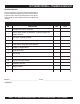
SCT SERIES TROWEL— TRAINING CHECKLIST TRAINING CHECKLIST This checklist will lists some of the minimum requirements for machine maintenance and operation. Please feel free to detach it and make copies. Use this checklist whenever a new operator is to be trained or it can be used as a review for more experienced operator’s. TRAINING CHECKLIST NO. DESCRIPTION 1 Read Operator’s Manual completely. 2 Machine layout, location of components, checking of engine and gearbox fluid level.
SCT SERIES TROWEL— DAILY PRE-OPERATION CHECKLIST DAILY PRE-OPERATION CHECKLIST DAILY PRE-OPERATION CHECKLIST 1 Engine Oil Level. 2 Gearbox Fluid Level. 3 Condition of Blades. 4 Blade Pitch Operation. 5 Safety Stop Switch Operation. COMMENTS: SCT SERIES WALK-BEHIND TROWEL — PARTS & OPERATION MANUAL — REV.
SCT SERIES TROWEL— SAFETY MESSAGE ALERT SYMBOLS FOR YOUR SAFETY AND THE SAFETY OF OTHERS! Safety precautions should be followed at all times when operating this equipment. Failure to read and understand the Safety Messages and Operating Instructions could result in injury to yourself and others. NOTE This Owner's Manual has been developed to provide complete instructions for the safe and efficient operation of the SCT SERIESWALK-BEHIND TROWEL.
SCT SERIES TROWEL— SAFETY MESSAGE ALERT SYMBOLS Accidental Starting ALWAYS place the engine ON/OFF switch in the OFF position, when the trowel is not in use. Over Speed Conditions NEVER tamper with the factory settings of the engine governor or settings. Personal injury and damage to the engine or equipment can result if operating in speed ranges above maximum allowable. Respiratory Hazard ALWAYS wear approved respiratory protection.
SCT SERIES TROWEL — RULES FOR SAFE OPERATION CAUTION: Failure to follow instructions in this manual may lead to serious injury or even death! This equipment is to be operated by trained and qualified personnel only! This equipment is for industrial use only. The following safety guidelines should always be used when operating the SCT SERIESwalk-behind trowel. SAFETY ■ DO NOT operate or service this equipment before reading this entire manual.
SCT SERIES TROWEL — RULES FOR SAFE OPERATION ■ DO NOT operate this trowel unless all guards and safety devices are attached and in place. See Pages 16 and 17. ■ ALWAYS use proper lifting techniques when moving the trowel. ■ ALWAYS check to make sure that the operating area is clear before starting the engine. ■ ALWAYS test the safety safety stop switch devices before operating the trowel. ■ NEVER place your feet or hands inside the guard rings while starting or operating this equipment.
SCT SERIES TROWEL — OPERATION AND SAFETY DECALS Machine Safety Decals The SCT SERIESwalk-behind trowel is equipped with a number of safety decals. These decals are provided for operator safety and maintenance information. Figure 1 below illustrates these decals as they appear on the machine. Should any of these decals become unreadable, replacements can be obtained from your dealer. Figure 1. SCT SERIESTrowel Decals PAGE 12 — SCT SERIES WALK-BEHIND TROWEL— PARTS & OPERATION MANUAL — REV.
SCT SERIES TROWEL — SPECIFICATIONS (TROWEL) Side View Top View Figure 2. SCT SERIESTrowel Dimensions Table 1. STOW Trowel Specifications MODEL SCT36 SCT46 A– Height (Lifting Hook) 36.7 in. (931.6 mm) 34.5 in. (876.2 mm) B– Height Engagement Lever) 41.4 in. (1,044.2 mm) 41.1 in. (1,044.2 mm) 36.5 in. (927.1 mm) 46.0 in. (1,168.4 mm) C–Width 70.5 in. (1,789.4 mm) 75.2 in. (1,910.1 mm) D–Length Weight – Operating SEE TABLE 3 1 Sound Pressure 94 db 97 db Vibration2 2.0g (19.6 m/s2) 2.5g (24.
SCT SERIES TROWEL— SPECIFICATIONS (ENGINES) Table 2. Specifications (Engines) Model HONDA GX160QX2 HONDA GX240K1QA2 HONDA GX340K1QAP2 Type Air-cooled 4 stroke, Single Cylinder, OHV, Horizontal Shaft Gasoline Engine Air-cooled 4 stroke, Single Cylinder, OHV, Horizontal Shaft Gasoline Engine Air-cooled 4 stroke, Single Cylinder, OHV, Horizontal Shaft Gasoline Engine Bore X Stroke 2.7 in. x 1.8 in. (68 mm x 45 mm) 2.9 in. x 2.3 in. (73 mm x 58 mm) 3.2 in. x 2.5 in. (82 mm x 64 mm) Displacement 9.
SCT SERIES TROWEL— GENERAL INFORMATION SCT SERIESWalk-Behind Trowel Familiarization Blades This walk-behind trowel is designed for the floating and finishing of concrete slabs. The blades of the trowel finish the concrete as they are rotated around the surface. Blades are classified as combination (8 inches wide), float (10 or 8 inches wide), and finish (6 inches wide).
SCT SERIES TROWEL— CONTROLS AND COMPONENTS Figure 3. SCT SERIESWalk-Behind Trowels Figures 3 shows the location of the basic controls or components, for the SCT SERIEStrowel. Listed below is a brief explanation of each control or component 1. Pitch Control - Turn this "Star Wheel" clockwise for increase blade pitch, and counter-clockwise for decrease blade pitch 2. Hand Grip/Handle Bar – When operating the trowel, place both hands on each grip to maneuver the trowel.
SCT SERIES TROWEL— BASIC ENGINE Figure 4. Engine Controls and Components INITIAL SERVICING (ENGINE) 5. The engine (Figure 4) must be checked for proper lubrication and filled with fuel prior to operation. Refer to the manufacturers engine manual for instructions & details of operation and servicing. Fuel Valve Lever – OPEN to let fuel flow, CLOSE to stop the flow of fuel. 6. Choke Lever – Used in the starting of a cold engine, or in cold weather conditions. The choke enriches the fuel mixture. 7.
SCT SERIES TROWEL — ASSEMBLY AND INSTALLATION Assembly and Installation Before the trowel can be put into operation there are some components that must be installed before the trowel can be used. This section provided general instructions on how to install those components. Handle Tube Installation 1. 2. Connect the throttle cable to the engine. (Figure 7). (The air cleaner housing may have to be removed to provide access for throttle cable installation.
SCT SERIES TROWEL — ASSEMBLY AND INSTALLATION Safety Stop Wire Locate the SAFETY STOP wire protruding from the handle tube (Figure 8) and connect it to the tail wire on the engine. Test the safety stop switch to insure proper operation. Figure 10. Blade Pitch Cable 2. Remove one brass set nut from the blade pitch cable end as shown in (Figure 10). 3. Thread the second brass set nut towards the cable as far as possible. 4.
SCT SERIES TROWEL— PRE-INSPECTION CAUTION NEVER operate the trowel in a confined area or enclosed area structure that does not provide ample free flow of air. ALWAYS wear approved eye and hearing protection before operating the trowel. NEVER place hands or feet inside the guard rings while the engine is running. ALWAYS shut the engine down before performing any kind of maintenance service on the trowel. Figure 12. Engine Oil Dipstick (Removal) 3.
SCT SERIES TROWEL— PRE-INSPECTION V-belt Check Explosive Fuel A worn or damaged V-belt can adversely affect the performance of the trowel. If a V-belt is defective or worn simply replace the Vbelt as outlined in the maintenance section of this manual. CAUTION Motor fuels are highly flammable and can be dangerous if mishandled. DO NOT smoke while refueling. DO NOT attempt to refuel the trowel if the engine is hot! or running. Blade Check Fuel Check Check for worn or damaged blades.
SCT SERIE STROWEL — INITIAL START-UP This section is intended to assist the operator with the initial start-up of the walk-behind trowel. It is extremely important that this section be read carefully before attempting to use the trowel in the field. CAUTION The trowel must be stabilized by the person carrying the operator’s handle (Figure 16). If it is not stabilized properly the handle may swing around and flip the trowel, thus causing damage to the trowel and bodily injury.
SCT SERIES TROWEL — INITIAL START-UP 3. Place the centrifugal safety stop switch (Figure 19) in the "ON" position. CAUTION NEVER disable or disconnect the centrifugal safety stop switch. It is provided for the operators’ safety and injury may result if it is disabled, disconnected or improperly maintained. Figure 21. Starter Grip 6. If the engine has started, slowly return the choke lever (Figure 20) to the "OPEN" position. If the engine has not started repeat steps 1 through 5. 7.
SCT SERIES TROWEL — OPERATION The following steps are intended as a basic guide to machine operation, and are not to be considered a complete guide to concrete finishing. We suggest that all operators, (experienced and novice), read “Slabs on Grade” published by the American Concrete Institute, Detroit, Michigan. Read the “Training” section of this manual for more information. PITCHING THE BLADES 1. To pitch the blades upwards using the "Standard" handle, (Figure 23) simply turn the star-wheel clockwise.
SCT SERIES TROWEL — OPTIONS Clip-On Float Blades (Optional) Blades Blades should be changed when they fail to finish concrete in a satisfactory manner. NOTE Blades are a vital part of finishing concrete. This trowel, or finisher, has been designed to finish concrete and the blades are built to stringent quality standards out of the finest trowel steel. If you need replacement blades, consult your parts list in this manual for part numbers and order them from your Multiquip parts dealer or importer.
SCT SERIES TROWEL — MAINTENANCE (ENGINE) QP40TH — MAINTENANCE (ENGINE) Engine Maintenance Perform engine maintenance procedures as referenced by Table 5 below: Table 5. Engine Maintenance Schedule DESCRIPTION (3) OPERATION BEFORE CHECK X EVERY FIRST MONTH 3 MONTHS OR OR 10 HRS. 25 HRS. EVERY 6 MONTHS OR 50 HRS. EVERY YEAR OR 100 HRS. EVERY 2 YEARS OR 200 HRS.
SCT SERIES TROWEL — MAINTENANCE (ENGINE) Maintenance DANGER : Perform the engine maintenance procedures as indicated below: DAILY ■ Thoroughly remove dirt and oil from the engine and control area. Clean or replace the air cleaner elements as necessary. Check and retighten all fasteners as necessary. Check the spring box and bellows for oil leaks. Repair or replace as needed. WEEKLY ■ Remove the fuel filter cap and clean the inside of the fuel tank. ■ Remove or clean the filter at the bottom of the tank.
SCT SERIES TROWEL — MAINTENANCE Trowel Arm Adjustment Procedure See the engine manual supplied with your machine for appropriate engine maintenance schedule and troubleshooting guide for problems. NOTE At the front of the book (Page 7) there is a “Daily Pre-Operation Checklist ”. Make copies of this checklist and use it on a daily basis. CAUTION! ALWAYS allow the engine to cool before servicing. NEVER attempt any maintenance work on a hot! engine. MAINTENANCE SCHEDULE Daily (8-10 Hours) 1.
SCT SERIES TROWEL — MAINTENANCE 2. Start engine, and bring trowel blades up to full speed and look for the following conditions: ■ Does the trowel have a perceived rolling or bouncing motion when in use? ■ Look at the trowel while it is running, does the guard ring “rock up and down” relative to the ground? Spider Removal b. Loosen the jam nut and cone point square head set screw, and carefully lift the upper trowel assembly off of the spider assembly.
SCT SERIES TROWEL — MAINTENANCE 3. Should the trowel arm inserts (bronze bushing ) come out with the trowel arm, remove the bushing from the trowel arm and set aside in a safe place. If the bushing is retained inside the spider plate, carefully remove the bushing. 4. Examine the bronze trowel arm bushing insert (Figure 38), and clean if necessary. Replace the bushing if out-of-round or worn. Trowel Arm Flatness Test 1.
SCT SERIES TROWEL — MAINTENANCE Trowel Arm Adjustment Shown in Figure 41 is the adjustment fixture with a trowel arm inserted. As each trowel arm is locked into the fixture, the arm bolt is adjusted to where it contacts a stop on the fixture. This will consistently adjust all of the trowel arms, keeping the finisher as flat and evenly pitched as possible. 1. Locate the trowel arm adjustment tool P/N 1817.
SCT SERIES TROWEL — MAINTENANCE Testing V-Belt Inspection and Replacement 1. Place trowel in test area, start engine and test trowel for smoothness. Inspect the v-belt for wear, fraying and deteriorization. Replace with the appropriate size belt as follows: 5.5 HP Models: P/N 01390 2. If trowel bounces has excessive vibration or does not run smoothly repeat alignment procedure.
SCT SERIES TROWEL — TROUBLESHOOTING (TROWEL) TABLE 6. TROWEL TROUBLESHOOTING SYMPTOM Engine running rough or not at all. Safety Stop Switch not functioning. If trowel “bounces, rolls concrete, or makes uneven swirls in concrete”. Machine has a perceptible rolling motion while running. POSSIBLE PROBLEM SOLUTION Safety Stop Switch malfunction? Make sure that the Safety Stop Switch is ON or replace switch if necessary. Fuel? Look at the fuel system.
SCT SERIES TROWEL — TROUBLESHOOTING (TROWEL) TABLE 6. TROWEL TROUBLESHOOTING (CONTINUED) SYMPTOM Sluggish response to engine speed change. POSSIBLE PROBLEM SOLUTION Worn V-belts? Replace V-belt. Dir ty centrifugal clutch? Disassemble and clean clutch. Defective or worn out centrifugal clutch? Replace entire clutch. Worn bearings in gearbox? Rotate input shaft by hand. If shaft rotates with difficulty, check the input and output shaft bearings. Replace as necessary.
SCT SERIES TROWEL — TROUBLESHOOTING (ENGINE) TABLE 7. ENGINE TROUBLESHOOTING (CONTINUED) SYMPTOM POSSIBLE PROBLEM SOLUTION Difficult to start Fuel is available but spark plug will not ignite. (Power available at high tension cable). Fuel is available but spark plug will not ignite. (Power NOT available at high tension cable). Fuel is available and spark plug ignites (compression normal). Fuel is available and spark plug ignites (compression low ). Ignition plug being bridge? Check ignition system.
EXPLANATION OF CODE IN REMARKS COLUMN The following section explains the different symbols and remarks used in the Parts section of this manual. Use the help numbers found on the back page of the manual if there are any questions. The contents and part numbers listed in the parts section are subject to change without notice . Multiquip does not guarantee the availibility of the parts listed. PART NO. PART NAME QTY. 12345 BOLT ....................... 1.... WASHER, 1/4 IN. ........... 12347 WASHER, 3/8 IN.
SCT SERIES TROWEL — SUGGESTED SPARE PARTS SCT SERIESTROWEL 1 TO 3 UNITS 1 to 3 Units Qty. ........ P/N .............................. Description 3 ............ 20478 .................... GRIP 2 ............ 20856 .................... SAFETY SWITCH 1 ............ 20285 .................... PITCH CONTROLCABLE 1 ............ 20514 .................... SAFETY STOP WIRE 1 ............ 30033-401 ............ THROTTLE CABLE 4 ............ 1157 A .................. BUSHING 4 ............ 2828 ....................
SCT SERIES TROWEL — DECAL LOCATOR NAMEPLATES AND DECALS PAGE 38 — SCT SERIES WALK-BEHIND TROWEL— PARTS & OPERATION MANUAL — REV.
SCT SERIES TROWEL — DECAL LOCATOR NAMEPLATE AND DECALS NO. 1 PART NO. 2 3 4 5 6 7 8 9 10 11 12 13 14 30053-001 25349-001 30054-001 25264-001 11246 25265-001 11246 11246 11247 11246 25378-001 11246 11246 PART NAME QTY. REMARKS NAMEPLATE .......................................................... 1 ....... CONTACT MULTIQUIP .......................................................................................... PARTS DEPT.
SCT SERIESTROWEL — STANDARD HANDLE STANDARD HANDLE 4 19 5 8 15 3 6 7 13 2 1 18 DETAIL “A” 14 SEE DETAIL “B” 19 20 17 SEE 21 DETAIL “A” 10 11 20 16 9 12 1 28 25 25 24 26 22 29 23 ASM 25 24 26 25 26 DETAIL “B” 30 27 CABLE LENGTH IS PRESET AND 1 ATTACHED TO THROTTLE LEVER AT THE FACTORY. ORDERABLE AS A UNIT ONLY. PAGE 40 — SCT SERIES WALK-BEHIND TROWEL— PARTS & OPERATION MANUAL — REV.
SCT SERIESTROWEL — STANDARD HANDLE STANDARD HANDLE NO. 1 2 3 * 4 * 5 * 6 * 7 * 8 * 9 * 10 11 12 13 14 15 16 17 18 19# 20# 21 22 23 24 25 26 27 28 29 30 PART NO. 20478 21251 30115-001 1729 21248 3615 21282 21279 0122C 06827-006 10019 30033-401 0786 0786A 21249 20285 21250 20856 1602 20988 20514 21254 21150 0169 10136 10133 1493 1247 1245 1116 PART NAME QTY.
SCT SERIES TROWEL — 4-BLADE SPIDER ASSY. 4 BLADE SPIDER ASSY. PAGE 42 — SCT SERIES WALK-BEHIND TROWEL— PARTS & OPERATION MANUAL — REV.
SCT SERIES TROWEL — 4-BLADE SPIDER ASSY. 4 BLADE SPIDER ASSY. NO. 1 * 2 * 3 * 4 # * 5 * 6% 7% 8% 9% 10% 11% 11% 12% 12% 13% 14% 15% 16% 17% 18% 19% 20% 21% 22 23 PART NO. 12208 12778 10793 1471 1154A 1157A 0164B 4164 1876 0166A 0105 0105 0161C 0161C 2828 1163 1316 1456 12097 1322 1162A 1875 1161 21261 10968 PART NAME QTY. REMARKS WEAR RING 1 FLANGE BEARING 1 THRUST COLLAR ............................................................. 1 ...........
SCT SERIES TROWEL — GEARBOX ASSY. GEARBOX ASSY. 1 12 2 1 13 3 34 8 4 5 4 6 7 7 36 11 9 7 6 14 2 10 31 15 17 32 16 18 30 6 19 20 33 37 GEARBOX ASSEMBLY 38 GASKET/SEAL KIT 39 BEARING KIT 35 32 QTY. 1 19 GEARBOX REQUIRES 22 OZ. OF LUBRICATING OIL FOR OPERATION. 18 31 GEARBOX OIL 22 0Z. 22 21 23 1 APPLY THREAD LOCK (LOCTITE 242 BLUE OR EQUIVALENT). 2 APPLY SEALANT (LOCTITE 572 OR EQUIVALENT). 3 TORQUE TO 15 LB/FT. 4 SHIM AS NECESSARY FOR 0.005 TO 0.
SCT SERIES TROWEL — GEARBOX ASSY. GEARBOX ASSY. NO. 1% * 2% 3% 4% * 5% PART NO. 0753 0131A 12876 20395 * 20397 20398 20399 20400 20401 6%# 20466 7%# 20465 8% 0627 9% 1851 10% 12874 11% 21218 12 1394 13 1480 14% 20476 15% 21033 16% 0121A 17% 1138 18%# 20475 19%# 20474 20% 1140 21% 20470 22% 1139 23 1238 24% 20402 * 20403 20404 20405 20406 25% 20396 * 26% 12875 27% 10235 28% 1146 29% 0254 * 1150 30 31 20802 32 20803 33 20801 34 16045 35 0655 36 0300B 37 21219 38 21046 39 21047 PART NAME QTY.
SCT SERIESTROWEL — GUARD RING ASSY. GUARD RING ASSY. PAGE 46 — SCT SERIES WALK-BEHIND TROWEL— PARTS & OPERATION MANUAL — REV.
SCT SERIESTROWEL — GUARD RING ASSY. GUARD RING ASSY. NO. PART NO. PART NAME 1 2 21119 21122 RING, STATIONARY GUARD, 36" RING, STATIONARY GUARD, 46" QTY. REMARKS 1 1 SCT SERIES WALK-BEHIND TROWEL — PARTS & OPERATION MANUAL — REV.
SCT SERIESTROWEL — STABILIZER RING ASSY. STABILIZER RING ASSY. 4 SEE DETAIL “A” DETAIL “A” 3 1 2 1 1 APPLY LOCTITE 242 BLUE OR EQUIVALENT. PAGE 48 — SCT SERIES WALK-BEHIND TROWEL— PARTS & OPERATION MANUAL — REV.
SCT SERIESTROWEL — STABILIZER RING ASSY. STABILIZER RING ASSY. NO PART NO PART NAME 1 2 3 4 1237 0161C 21465-001 21471-351 SCREW, SHC 5/16-18 X 3/4 WASHER, LOCK, 5/16 MED FLANGE, BEARING STABILIZER RING ASSEMBLY QTY. REMARKS 4 4 4 1 SCT SERIES WALK-BEHIND TROWEL — PARTS & OPERATION MANUAL — REV.
SCT SERIES TROWEL — ENGINES, 5.5 HP, 8 HP, 11 HP HONDA ASSY. ENGINE, 5.5 HP, 8 HP, 11 HP HONDA ASSY. PAGE 50 — SCT SERIES WALK-BEHIND TROWEL— PARTS & OPERATION MANUAL — REV.
SCT SERIES TROWEL — ENGINES, 5.5 HP, 8 HP, 11 HP HONDA ASSY. ENGINE, 5.5 HP, 8 HP, 11 HP HONDA ASSY. NO. 1 1 1 2 3 4 5 5 6 7 8 9 10 10 11 11 12 13 14 15 16 17 18 19 20 21 22*# 23*# 24*# 25*# 26*# 27* 28*# 29#* 30# PART NO. 1386 1387 1388 1391 0161C 0300B 21293 30043-351 0627 1834 1273 10229 0255 0250 1390 0152-3 30102-002 0948 10031 131A 1488 1475 21140 21141 21256 0256 0251 0458 0454 0855 0253 1868 0456 0252 0457 PART NAME QTY. REMARKS ENGINE 5.
SCT SERIESTROWEL — BLADES & ADJUSTMENT FIXTURE ASSY. (OPTIONS) BLADES & ADJUSTMENT FIXTURE ASSY. PAGE 52 — SCT SERIES WALK-BEHIND TROWEL— PARTS & OPERATION MANUAL — REV.
SCT SERIESTROWEL — BLADES & ADJUSTMENT FIXTURE ASSY. BLADES & ADJUSTMENT FIXTURE ASSY. NO. PART NO. PART NAME 1 1 2 3 3 4 5 6 7 8 9 10 10 11 11 12 13 14 15 16 17 18 19 20 21 0201 0202 1434 0487 0490 0489 0488 QTY. REMARKS COMBO FLOAT & FINISH BLADE .......................... 4 ......... CONTACT UNIT SALES DEPT./ACCESSORY ITEM ENDURO COMBO FLOAT &FINISH BLADE .......... 4 ......... CONTACT UNIT SALES DEPT./ACCESSORY ITEM FLOAT BLADE ........................................................ 4 .........
HONDA GX160K1QX2 — AIR CLEANER ASSY. AIR CLEANER ASSY. PAGE 54 — SCT SERIES WALK-BEHIND TROWEL— PARTS & OPERATION MANUAL — REV.
HONDA GX160K1QX2 — AIR CLEANER ASSY. AIR CLEANER ASSY. NO. 1 2 3 4 5 6 7 8 9 11 PART NO. 16271ZE1000 17210ZE1505 17218ZE1821 17230ZE1820 17232891000 17238ZE7010 17239ZE1000 17410ZE1020 90201415000 90325044000 12 13 90325044000 957010602000 PART NAME QTY. REMARKS GASKET, ELBOW 1 ELEMENT, AIR CLEANER (DUAL) 1 FILTER, OUTER 1 COVER, AIR CLEANER (DUAL) 1 GROMMET, AIR CLEANER 1 COLLAR, AIR CLEANER 2 COLLAR B, AIR CLEANER 1 ELBOW, AIR CLEANER 1 NUT, CAP 6MM 2 WINGNUT, TOOL BOX SETTING ........................
HONDA GX160K1QX2 — CAMSHAFT ASSY. CAMSHAFT ASSY. PAGE 56 — SCT SERIES WALK-BEHIND TROWEL— PARTS & OPERATION MANUAL — REV.
HONDA GX160K1QX2 — CAMSHAFT ASSY. CAMSHAFT ASSY. NO. 1 2 3 4 PART NO. 14100ZE1812 14410ZE1010 14431ZE1000 14441ZE1000 4 5 6 7 8 9 10 11 12 13 14 15 14441ZE1010 14451ZE1013 14568ZE1000 14711ZF1000 14721ZF1000 14751ZF1000 14771ZE1000 14773ZE1000 14781ZE1000 14791ZE1010 90012ZE0010 90206ZE1000 PART NAME QTY. REMARKS CAMSHAFT ASSEMBLY 1 ROD, PUSH 2 ARM, VALVE ROCKER 2 LIFTER, VALVE ..................................................... 2 ...........
HONDA GX160K1QX2 — CARBURETOR ASSY. CARBURETOR ASSY. PAGE 58 — SCT SERIES WALK-BEHIND TROWEL— PARTS & OPERATION MANUAL — REV.
HONDA GX160K1QX2 — CARBURETOR ASSY. CARBURETOR ASSY. NO. 1 #+%■ * 2 * 3 4 PART NO.
HONDA GX160K1QX2 — CONTROL ASSY. CONTROL ASSY. PAGE 60 — SCT SERIES WALK-BEHIND TROWEL— PARTS & OPERATION MANUAL — REV.
HONDA GX160K1QX2 — CONTROL ASSY. CONTROL ASSY. NO. 2 PART NO. 16500ZH8823 4 5 6 7 8 * 9 * 10 * 11 * 12 * 13 16551ZE0010 16555ZE1000 16561ZE1020 16562ZE1020 16571ZH8020 16574ZE1000 16575ZH8000 16576891000 16578ZE1000 16580ZH8812 18 19 * 22 * 23 * 24 16584883300 16592ZE1810 90013883000 90016ZE5010 90114SA0000 93500050250H 938930501600 9405006000 * 14 * 15 * 17 PART NAME QTY. REMARKS CONTROL ASSEMBLY, REMOTE......................... 1............ INCLUDES ITEMS W/ * .....................................
HONDA GX160K1QX2 — CRANKCASE COVER ASSY. CRANKCASE COVER ASSY. PAGE 62 — SCT SERIES WALK-BEHIND TROWEL— PARTS & OPERATION MANUAL — REV.
HONDA GX160K1QX2 — CRANKCASE COVER ASSY. CRANKCASE COVER ASSY. NO. 1 3 4 5 9 10 11 * 12 13 14 * PART NO. 11300ZE1641 11381ZH8801 15600ZE1003 15600ZG4003 15625ZE1003 15625ZE1003 91202883005 9430108140 957010803200 961006205000 PART NAME QTY. REMARKS COVER ASSEMBLY, CRANKCASE (U- TYPE) ..... 1 ...........
HONDA GX160K1QX2 — CRANKSHAFT ASSY. CRANKSHAFT ASSY. PAGE 64 — SCT SERIES WALK-BEHIND TROWEL— PARTS & OPERATION MANUAL — REV.
HONDA GX160K1QX2 — CRANKSHAFT ASSY. CRANKSHAFT ASSY. NO. 3 9 PART NO. 13310ZE1601 90745ZE1600 PART NAME CRANKSHAFT, Q- TYPE KEY, 4.78 X 4,78 X 38 QTY. 1 1 REMARKS SCT SERIES WALK-BEHIND TROWEL — PARTS & OPERATION MANUAL — REV.
HONDA GX160K1QX2 — CYLINDER BARREL ASSY. CYLINDER BARREL ASSY. PAGE 66 — SCT SERIES WALK-BEHIND TROWEL— PARTS & OPERATION MANUAL — REV.
HONDA GX160K1QX2 — CYLINDER BARREL ASSY. CYLINDER BARREL ASSY. NO. 2 3 4 * 5 # * 6 # * 8 * 9 10 11 * 12 13 * 14% 15% 16 17 18 * 19 20 PART NO. 12000ZH8811 15510ZE1033 16510ZE1000 16511ZE1000 16512ZE1000 16531ZE1000 16541ZE1000 90131ZE1000 80451ZE1000 90601ZE1000 90602ZE1000 91001ZF1003 91202883005 91353671003 9405010000 9410106800 9425108000 957010601200 PART NAME QTY. REMARKS CYLINDER ASSEMBLY, OIL ALERT .................... 1............ INCLUDES ITEMS W/ * SWITCH ASSEMBLY, OIL LEVEL ...................
HONDA GX160K1QX2 — CYLINDER HEAD ASSY. CYLINDER HEAD ASSY. PAGE 68 — SCT SERIES WALK-BEHIND TROWEL— PARTS & OPERATION MANUAL — REV.
HONDA GX160K1QX2 — CYLINDER HEAD ASSY. CYLINDER HEAD ASSY. NO. 1 2 * 3 * 4% 5 6 7 8 9 10 11 12 14 15 PART NO. 12210ZH8000 12204ZE1306 12205ZE1315 12216ZE5300 12251ZF1800 12310ZE1010 12391ZE1000 15721ZH8000 90016ZE1000 90043ZE1020 90047ZE1000 9430110160 957230806000 9807956846 PART NAME QTY. REMARKS CYLINDER HEAD .................................................. 1............ INCLUDES ITEMS W/ * GUIDE, VALVE OS (OPTIONAL 1 GUIDE, EXHAUST VALVE OS (OPTIONAL) ......... 1............
HONDA GX160K1QX2 — FAN COVER ASSY. FAN COVER ASSY. PAGE 70 — SCT SERIES WALK-BEHIND TROWEL— PARTS & OPERATION MANUAL — REV.
HONDA GX160K1QX2 — FAN COVER ASSY. FAN COVER ASSY. NO. 2 4 7 8 10 11 13 14 17 19 PART NO. 19610ZE1000ZC 19611ZH8810 90601ZH7013 19630ZH8000 32197ZH8003 36100ZE1015 90013883000 90022888010 34150ZH7003 957010600800 PART NAME COVER, FAN "NH1" (BLACK) PLATE, SIDE (OIL ALERT) CLIP, HARNESS SHROUD SUB- HARNESS SWITCH ASSEMBLY, ENGINE STOP BOLT, FLANGE 6 X12 (CT200) BOLT, FLANGE 6 X20 (CT200) ALERT UNIT, OIL BOLT, FLANGE 6 X8 QTY.
HONDA GX160K1QX2 — FLYWHEEL ASSY. FLYWHEEL ASSY. PAGE 72 — SCT SERIES WALK-BEHIND TROWEL— PARTS & OPERATION MANUAL — REV.
HONDA GX160K1QX2 — FLYWHEEL ASSY. FLYWHEEL ASSY. NO. 1 2 4 5 5 8 PART NO. 13331357000 19511ZE1000 28451ZH8003 31100ZE1010 31100ZE1810 90201878003 PART NAME KEY, SPECIAL WOODRUFF (25 X18) FAN, COOLING PULLEY, STARTER FLYWHEEL FLYWHEEL, LAMP NUT, SPECIAL 14MM QTY. 1 1 1 1 1 1 REMARKS SCT SERIES WALK-BEHIND TROWEL — PARTS & OPERATION MANUAL — REV.
HONDA GX160K1QX2 — FUEL TANK ASSY. FUEL TANK ASSY. PAGE 74 — SCT SERIES WALK-BEHIND TROWEL— PARTS & OPERATION MANUAL — REV.
HONDA GX160K1QX2 — FUEL TANK ASSY. FUEL TANK ASSY. NO. 1 2 3 3 5 6 * 11 12 13 14 15 PART NO. 16854ZH8000 16955ZE1000 17510ZE1020ZB 17510ZE1020ZF 17620ZH7023 17631ZH7003 91353671003 9405006000 950014500360M 9500202080 957010602500 PART NAME QTY. REMARKS RUBBER, SUPPORTER 107MM 1 JOINT, FUEL TANK 1 TANK, FUEL *R8* (BRIGHT RED) 1 TANK, FUEL *NH1* (BLACK) 1 CAP, FUEL FILLER ............................................... 1 ........... INCLUDES ITEM W/ * GASKET, FUEL FILLER CAP 1 O- RING 13.5 X1.
HONDA GX160K1QX2 — IGNITION COIL ASSY. IGNITION COIL ASSY. PAGE 76 — SCT SERIES WALK-BEHIND TROWEL— PARTS & OPERATION MANUAL — REV.
HONDA GX160K1QX2 — IGNITION COIL ASSY. IGNITION COIL ASSY. NO. 1 2 7 11 PART NO. 30500ZE1033 30700ZE1013 36101ZE1010 90121952000 PART NAME COIL ASSEMBLY, IGNITION CAP ASSEMBLY, NOISE SUPPRESSOR WIRE, STOP SWITCH 370MM BOLT, FLANGE 6 X25 QTY. 1 1 1 2 REMARKS SCT SERIES WALK-BEHIND TROWEL — PARTS & OPERATION MANUAL — REV.
HONDA GX160K1QX2 — MUFFLER ASSY. MUFFLER ASSY. PAGE 78 — SCT SERIES WALK-BEHIND TROWEL— PARTS & OPERATION MANUAL — REV.
HONDA GX160K1QX2 — MUFFLER ASSY. MUFFLER ASSY. NO. 1 1 3 7 8 11 12 15 PART NO. 18310ZF1000 18310ZH8810 18320ZF1H01 18355ZE1000 18381ZH8800 90050ZE1000 90055ZE1000 94001080000S PART NAME MUFFLER MUFFLER (OPTIONAL) PROTECTOR, MUFFLER ARRESTER, SPARK (OPTIONAL) GASKET, MUFFLER SCREW, TAPPING 5 X 8 (OPTIONAL SCREW, TAPPING 4 X 6 (OPTIONAL) NUT, HEX. 8MM QTY. 1 1 1 1 1 4 1 2 REMARKS SCT SERIES WALK-BEHIND TROWEL — PARTS & OPERATION MANUAL — REV.
HONDA GX160K1QX2 — PISTON ASSY. PISTON ASSY. PAGE 80 — SCT SERIES WALK-BEHIND TROWEL— PARTS & OPERATION MANUAL — REV.
HONDA GX160K1QX2 — PISTON ASSY. PISTON ASSY. NO. 1 1 1 1 1 1 1 1 2 2 2 2 3 4 4 5 6 PART NO. 13010ZF1023 13010ZH8941 13011ZF1023 13011ZH8941 13012ZF1023 13012ZH8941 13013ZF1023 13013ZH8941 13101ZH8000 13102ZH8000 13103ZH8000 13104ZH8000 13111ZE1000 132AOZE1000 13200ZE1010 90001ZE1000 90551ZE1000 PART NAME QTY. REMARKS RING SET, PISTON (STANDARD) ............................ 1 ........ USE UP TO ENG S/N 5495899 RING SET, PISTON (STANDARD) ............................ 1 ........
HONDA GX160K1QX2 — RECOIL STARTER ASSY. RECOIL STARTER ASSY. PAGE 82 — SCT SERIES WALK-BEHIND TROWEL— PARTS & OPERATION MANUAL — REV.
HONDA GX160K1QX2 — RECOIL STARTER ASSY. RECOIL STARTER ASSY. NO. 1 2 * 3 * 4 * 5 * 6 * 7 * 8 * 9 * 10 * 11 * 12 PART NO. 28400ZH8013ZB 28410ZH8003ZB 28420ZH8013 28422ZH8013 28433ZH8003 28441ZH8003 28442ZH8003 28443ZH8003 28461ZH8003 28462ZH8003 90003ZH8003 90008ZE2003 PART NAME QTY. REMARKS STARTER ASSY., RECOIL "NH1" BLACK ...................1 ............
NOTE PAGE PAGE 84 — SCT SERIES WALK-BEHIND TROWEL— PARTS & OPERATION MANUAL — REV.
HONDA GX160K1QX2 — GASKET KIT ASSY. GASKET KIT ASSY. NO. 1 * 2 * 3 * 4 * 5 * 6 * PART NO. 06111ZH8405 11381ZH8801 12251ZF1800 12391ZE1000 16212ZH8800 16221ZH8801 18381ZH8800 PART NAME QTY. REMARKS GASKET KIT ......................................................... 1............
HONDA GX160K1QX2 — ENGINE LABELS ASSY. ENGINE LABELS ASSY. PAGE 86 — SCT SERIES WALK-BEHIND TROWEL— PARTS & OPERATION MANUAL — REV.
HONDA GX160K1QX2 — ENGINE LABELS ASSY. ENGINE LABELS ASSY. NO. 1 PART NO. 87521ZH8020 2 87522ZE1810 3 6 7 8 15 87522ZH9000 87528ZE1810 87530ZH8810 87532ZH8810 887586ZH7W00 PART NAME QTY. REMARKS ENBLEM 5.5 .......................................................... 1 ........... USE FROM ENGINE SN 7438468 MARK, CAUTION (EXTERNAL) ............................ 1 ...........
HONDA GX240K1QA2 ENGINE — AIR CLEANER ASSY. AIR CLEANER ASSY. PAGE 88 — SCT SERIES WALK-BEHIND TROWEL— PARTS & OPERATION MANUAL — REV.
HONDA GX240K1QA2 ENGINE — AIR CLEANER ASSY. AIR CLEANER ASSY. NO. 1 2 3 * 5 6 8% 9% 10 13 14 15 PART NO. 16271ZE2000 17210ZE2822 17218ZE2505 17231ZH9820 17232891000 17238ZE2310 17239ZE1000 17410ZE2020 90325044000 90009ZE2003 9405006000 PART NAME QTY. REMARKS GASKET, ELBOW 1 ELEMENT, AIR CLEANER, DUAL ............. 1 ............. INCLUDES ITEMS W/ * FILTER, OUTER 1 COVER, AIR CLEANER 1 GROMMET, AIR CLEANER 1 COLLAR, AIR CLEANER 2 COLLAR B, AIR CLEANER 1 ELBOW COMP., AIR CLEANER ............... 1 .........
HONDA GX240K1QA2 ENGINE — CAMSHAFT ASSY. CAMSHAFT ASSY. PAGE 90 — SCT SERIES WALK-BEHIND TROWEL— PARTS & OPERATION MANUAL — REV.
HONDA GX240K1QA2 ENGINE — CAMSHAFT ASSY. CAMSHAFT ASSY. NO. 1 2 3 4 5 6 * 7 8 9 10 11 12 13 14 15 PART NO. 14100ZE2W01 14410ZE2013 14431ZE2010 14441ZE2000 14451ZE1013 14568ZE1000 14711ZE2000 14721ZE2000 14751ZE2003 14771ZE2000 14773ZE2000 14781ZE2000 14791ZE2010 90012ZE0010 90206ZE1000 PART NAME QTY. REMARKS CAMSHAFT ASSY. ................................... 1 ............. INCLUDES ITEMS W/ * ROD PUSH 2 ARM VALVE ROCKER 2 LIFTER VALVE 2 PIVOT ROCKER ARM 2 SPRING, WEIGHT RETURN 1 VALVE, IN. 1 VALVE, EX.
HONDA GX240K1QA2 ENGINE — CARBURETOR ASSY. CARBURETOR ASSY. PAGE 92 — SCT SERIES WALK-BEHIND TROWEL— PARTS & OPERATION MANUAL — REV.
HONDA GX240K1QA2 ENGINE — CARBURETOR ASSY. CARBURETOR ASSY. NO. 1 %+ * 2 * 3 * 5 * 6 + * 7 * 8 * 9 10 * 11 * 12 * 13 * 14 15 16 17 18 19 * 20 * 21 * 22 * 23 * 24 25■ 26 26 26 * 27 * 28 * PART NO.
HONDA GX240K1QA2 ENGINE — CONTROL ASSY. CONTROL ASSY. PAGE 94 — SCT SERIES WALK-BEHIND TROWEL— PARTS & OPERATION MANUAL — REV.
HONDA GX240K1QA2 ENGINE — CONTROL ASSY. CONTROL ASSY. NO. 1 2 3 4 5 8 10 * 11 * 12 * 13 * 14 * 15 * 16 * 17 * 19 20 21 24 * 26 * 27 PART NO. 16550ZE2700 16551ZE2000 16555ZE2000 16561ZE2000 16562ZE2000 16570ZE2W20 16571ZE2W00 16574ZE1000 16575ZE2W00 16576891000 16578ZE1000 16581ZE2W00 16584883300 16592883310 90013883000 90015ZE5010 90114SA0000 93500050280A 93500050160A 9405006000 PART NAME QTY.
HONDA GX240K1QA2 ENGINE — CRANKCASE COVER ASSY. CRANKCASE COVER ASSY. PAGE 96 — SCT SERIES WALK-BEHIND TROWEL— PARTS & OPERATION MANUAL — REV.
HONDA GX240K1QA2 ENGINE — CRANKCASE COVER ASSY. CRANKCASE COVER ASSY. NO. 2 3 4 5 8+ 9% 10 * 11 $ * 12 $ * 13 $ * 14 * 15 * 16 * 17 18 * 19 * 20 21 * 22 * PART NO. 11400ZE2601 11381ZE2801 15600ZG4003 15600735003 15625ZE1000 15625ZE1003 16510ZE2811 16511ZE2000 16512ZE2811 16513ZE2000 16531ZE2000 90473147000 90602ZE1000 90701HC4000 91201890003 9410106800 957010803500 961006202000 961006206000 PART NAME QTY. REMARKS COVER ASSY., CRANKCASE .................. 1 .............
HONDA GX240K1QA2 ENGINE — CRANKSHAFT ASSY. CRANKSHAFT ASSY. PAGE 98 — SCT SERIES WALK-BEHIND TROWEL— PARTS & OPERATION MANUAL — REV.
HONDA GX240K1QA2 ENGINE — CRANKSHAFT ASSY. CRANKSHAFT ASSY. NO. 2 8 10 12 * PART NO. 13320ZE2601 13351ZE2010 90745ZE2600 961006206000 PART NAME QTY. REMARKS CRANKSHAFT COMP., Q- TYPE .............. 1 ............. INCLUDES ITEMS W/ * WEIGHT, BALANCER 1 KEY 6.3 X 6.3 X 43 1 BEARING, RADIAL BALL 6206 1 SCT SERIES WALK-BEHIND TROWEL — PARTS & OPERATION MANUAL — REV.
HONDA GX240K1QA2 ENGINE — CYLINDER BARREL ASSY. CYLINDER BARREL ASSY. PAGE 100 — SCT SERIES WALK-BEHIND TROWEL— PARTS & OPERATION MANUAL — REV.
HONDA GX240K1QA2 ENGINE — CYLINDER BARREL ASSY. CYLINDER BARREL ASSY. NO. 1 3 6 7 8 * 11 12 14 * 15 16 PART NO. 12000ZE2834 16541ZE2010 90131896650 90446KE1000 91201890003 9410912000 9425110000 961006202000 90013883000 34150ZH7003 PART NAME QTY. REMARKS CYLINDER ASSY., BALANCER + OIL ALERT ...... 1 .......... INCLUDES ITEMS W/ * SHAFT, GOVERNOR ARM 1 BOLT, DRAIN PLUG 2 WASHER 8.2 X17X0.
HONDA GX240K1QA2 ENGINE — CYLINDER HEAD ASSY. CYLINDER HEAD ASSY. PAGE 102 — SCT SERIES WALK-BEHIND TROWEL— PARTS & OPERATION MANUAL — REV.
HONDA GX240K1QA2 ENGINE — CYLINDER HEAD ASSY. CYLINDER HEAD ASSY. NO. 1 2 * 3 * 4 * 5 6 7 8 10 11 12 13 14 15 16 17 17 17 17 PART NO. 12200ZH9000 12204ZE2306 12205ZE2305 12216ZE2300 12251ZE2800 12310ZE2020 12391ZE2020 14775ZE2010 90014ZE2000 90042ZE2000 92900080320E 90441ZE2010 9430112200 950051100130M 957011008000 9807955846 9807955855 9807956846 9807956855 PART NAME QTY. REMARKS CYLINDER HEAD COMP. ....................................... 1 ..........
HONDA GX240K1QA2ENGINE — FAN COVER ASSY. FAN COVER ASSY. PAGE 104 — SCT SERIES WALK-BEHIND TROWEL— PARTS & OPERATION MANUAL — REV.
HONDA GX240K1QA2ENGINE — FAN COVER ASSY. FAN COVER ASSY. NO. 1 2 3 4 5 7 9 PART NO. 16731ZE2003 19610ZE2010ZC 19631ZE2D00 32197ZH8003 36100ZH7003 90013883000 90684ZA0601 PART NAME CLIP, TUBE COVER COMP., FAN *NH1* BLACK SHROUD SUB-HARNESS SWITCH ASSY., ENGINE STOP BOLT, FLANGE 6X12, CT200 CLIP, WIRE HARNESS QTY. 1 1 1 1 1 6 1 REMARKS SCT SERIES WALK-BEHIND TROWEL — PARTS & OPERATION MANUAL — REV.
HONDA GX240K1QA2 ENGINE — FLYWHEEL ASSY. FLYWHEEL ASSY. PAGE 106 — SCT SERIES WALK-BEHIND TROWEL— PARTS & OPERATION MANUAL — REV.
HONDA GX240K1QA2 ENGINE — FLYWHEEL ASSY. FLYWHEEL ASSY. NO. 1 2 4 7 8 PART NO. 19511ZE2000 28450ZE2W11 31100ZE2010 90201ZE3V00 90741ZE2000 PART NAME FAN, COOLING PULLEY COMP., STARTER, SCREEN GRID FLYWHEEL COMP. NUT, SPECIAL 16MM KEY, SPECIAL WOODRUFF 25X18 QTY. 1 1 1 1 1 REMARKS SCT SERIES WALK-BEHIND TROWEL — PARTS & OPERATION MANUAL — REV.
HONDA GX240K1QA2ENGINE — FUEL TANK ASSY. FUEL TANK ASSY. PAGE 108 — SCT SERIES WALK-BEHIND TROWEL— PARTS & OPERATION MANUAL — REV.
HONDA GX240K1QA2ENGINE — FUEL TANK ASSY. FUEL TANK ASSY. NO. 1 2 3 5 6 * 8 11 12 13 14 15 PART NO. 16854ZH8000 16955ZE1000 17510ZE2020ZD 17620ZH7023 17631ZH7003 17672ZE2W01 91353671003 9405008000 950014500360M 9500202080 957010802500 PART NAME QTY. REMARKS RUBBER SUPPORTER 107MM 1 JOINT, FUEL TANK 1 TANK COMP., FUEL *NH1*, BLACK 1 CAP COMP., FUEL FILLER .................................... 1 ..........
HONDA GX240K1QA2 ENGINE — IGNITION COIL ASSY. IGNITION COIL ASSY. PAGE 110 — SCT SERIES WALK-BEHIND TROWEL— PARTS & OPERATION MANUAL — REV.
HONDA GX240K1QA2 ENGINE — IGNITION COIL ASSY. IGNITION COIL ASSY. NO. 1 2 6 8 11 PART NO. 30500ZE2023 30700ZE1013 31512ZE2000 36101ZE1010 90015883000 PART NAME COIL ASSY., IGNITION CAP ASSY., NOISE SUPPRESSOR GROMMET, WIRE WIRE, STOP SWITCH 370MM BOLT, FLANGE 6X28 QTY. 1 1 1 1 2 REMARKS SCT SERIES WALK-BEHIND TROWEL — PARTS & OPERATION MANUAL — REV.
HONDA GX240K1QA2 ENGINE — MUFFLER ASSY. MUFFLER ASSY. PAGE 112 — SCT SERIES WALK-BEHIND TROWEL— PARTS & OPERATION MANUAL — REV.
HONDA GX240K1QA2 ENGINE — MUFFLER ASSY. MUFFLER ASSY. NO. 1 2 3 4 5 6 7 8 10 11 12 13 14 PART NO. 18310ZE2W00 18320ZE2W01 18323ZE2W00 18330ZE2W00 18331ZE2810 18333ZE3800 18355ZE2010 18381ZE2W10 90013883000 90050ZE1000 90055ZE1000 90050ZE1000 9405008000 PART NAME MUFFLER COMP. PROTECTOR COMP., MUFFLER PROTECTOR, EX. PIPE PIPE, EX. CAP, MUFFLER GASKET, EX. PIPE ARRESTER, SPARK GASKET, MUFFLER, ARRESTER BOLT, FLANGE 6X12 CT200 SCREW, TAPPING 5X8 SCREW, TAPPING 4X6 SCREW, TAPPING 5X8 NUT, FLANGE 8MM QTY.
HONDA GX240K1QA2 ENGINE — PISTON ASSY. PISTON ASSY. PAGE 114 — SCT SERIES WALK-BEHIND TROWEL— PARTS & OPERATION MANUAL — REV.
HONDA GX240K1QA2 ENGINE — PISTON ASSY. PISTON ASSY. NO. 1 1 1 1 2 2 2 2 3 4 4 5 * 6 PART NO. 13010ZE2013 13011ZE2013 13012ZE2013 13013ZE2013 13101ZE2W00 13102ZE2W00 13103ZE2W00 13104ZE2W00 13111ZE2000 13200ZE2000 13200ZE2305 90001ZE8000 90551ZE1000 PART NAME QTY. REMARKS RING SET, PISTON, STD. 1 RING SET, PISTON, OS 0.25, OPTIONAL 1 RING SET, PISTON, OS 0.50, OPTIONAL 1 RING SET, PISTON, 0.75, OPTIONAL 1 PISTON, STANDARD 1 PISTON, OS 0.25, OPTIONAL 1 PISTON, OS 0.50, OPTIONAL 1 PISTON, 0.
HONDA GX240K1QA2 ENGINE — RECOIL STARTER ASSY. RECOIL STARTER ASSY. PAGE 116 — SCT SERIES WALK-BEHIND TROWEL— PARTS & OPERATION MANUAL — REV.
HONDA GX240K1QA2 ENGINE — RECOIL STARTER ASSY. RECOIL STARTER ASSY. NO. 1 2 * 3 * 4 * 5 * 6 * 7 * 8 * 10 * 11 * 13 * 14 PART NO. 28400ZE2W01ZB 28410ZE2W01ZB 28421ZE2W01 28422ZE2W01 28441ZE2W01 28442ZE2W01 28443ZE2W01 28444ZE2W01 28461ZE2W02 28462ZE2W11 90004ZE2W01 90008ZE2003 PART NAME QTY. REMARKS STARTER ASSY., RECOIL *NH1*, BLACK ................... 1 ....... INCLUDES ITEMS W/ * CASE COMP.
HONDA GX240K1QA2 ENGINE — ENGINE LABELS ENGINE LABELS PAGE 118 — SCT SERIES WALK-BEHIND TROWEL— PARTS & OPERATION MANUAL — REV.
HONDA GX240K1QA2 ENGINE — ENGINE LABELS ENGINE LABELS NO. 1 3 5 16 PART NO. 87521ZE2W01 87522ZH9000 87528ZE2810 87532ZH8810 PART NAME EMBLEM, INTERNAL LABEL, CAUTION MARK, CHOKE, EXTERNAL MARK, OIL ALERT, E QTY. 1 1 1 1 REMARKS SCT SERIES WALK-BEHIND TROWEL — PARTS & OPERATION MANUAL — REV.
HONDA GX-340K1QAP2 ENGINE — AIR CLEANER ASSY. AIR CLEANER ASSY. PAGE 120 — SCT SERIES WALK-BEHIND TROWEL— PARTS & OPERATION MANUAL — REV.
HONDA GX-340K1QAP2 ENGINE — AIR CLEANER ASSY. AIR CLEANER ASSY. NO. 1 2 3 * 4 5 * 6 7# 8# 9 11 12 13 14 PART NO. 16271ZE2000 17210ZE3505 17218ZE3505 17231ZE3W00 17232891000 17235ZH9N00 17238ZE2310 17239ZE1000 17410ZH9N00 90203ZA0800 90325044000 934040602008 9405006000 PART NAME QTY. REMARKS GASKET, ELBOW 1 ELEMENT, AIR CLEANER ............................... 1 ................
HONDA GX-340K1QAP2 ENGINE — CAMSHAFT ASSY. CAMSHAFT ASSY. PAGE 122 — SCT SERIES WALK-BEHIND TROWEL— PARTS & OPERATION MANUAL — REV.
HONDA GX-340K1QAP2 ENGINE — CAMSHAFT ASSY. CAMSHAFT ASSY. NO. 1 2 3 4 5 6 * 7 8 9 10 11 12 13 14 15 16 17 PART NO. 14100ZE3020 14410ZE3013 14431ZE2010 14441ZE2000 14451ZE1013 14568ZE1000 14711ZE3000 14721ZE3000 14751ZE2003 14771ZE2000 14773ZE2000 14775ZE2010 14781ZE2000 14791ZE2010 90012ZE0010 90206ZE1000 12209ZE8003 PART NAME QTY. REMARKS CAMSHAFT ASSEMBLY ................................. 1 ................
HONDA GX-340K1QAP2 ENGINE — CARBURETOR ASSY. CARBURETOR ASSY. PAGE 124 — SCT SERIES WALK-BEHIND TROWEL— PARTS & OPERATION MANUAL — REV.
HONDA GX-340K1QAP2 ENGINE — CARBURETOR ASSY. CARBURETOR ASSY. NO. 1 * 2 * 3 * 4 * 5 * 6 * 7 * 8 * 9 * 10 * 11 * 12 * 13 * 14 15 16 17 18 19 * 20 * 21 * 22 * 23 * 24 * 25# 26 * 26 * 26 * 27 * PART NO.
HONDA GX-340K1QAP2 ENGINE — CRANKCASE COVER ASSY. CRANKCASE COVER ASSY. PAGE 126 — SCT SERIES WALK-BEHIND TROWEL— PARTS & OPERATION MANUAL — REV.
HONDA GX-340K1QAP2 ENGINE — CRANKCASE COVER ASSY. CRANKCASE COVER ASSY. NO. 1 2 3 4 5 7 * 8% 9$ 10#♣$ 11#♣$ 12#♣$ 13♣$ 15♣$ 16 17$ 18♣$ 19 20$ 21$ PART NO. 06165ZE3000 11300ZE3602 11381ZE3801 15600ZG4003 15600735003 15625ZE1003 15625ZE1003 16510ZE3000 16511ZE8000 16512ZE3000 16513ZE2000 16531ZE2000 90602ZE1000 90701HC4000 91201ZE3004 9410106800 957010804000 961006202000 961006207000 PART NAME QTY. REMARKS GOVERNOR KIT (OPTIONAL) ......................... 1 ................ INCLUDES ITEMS W/♣ COVER ASSY.
HONDA GX-340K1QAP2 ENGINE — CONTROL ASSY. CONTROL ASSY. NO ART WORK AVAILABLE PAGE 128 — SCT SERIES WALK-BEHIND TROWEL— PARTS & OPERATION MANUAL — REV.
HONDA GX-340K1QAP2 ENGINE — CONTROL ASSY. CONTROL ASSY. NO. 2 3 4 5 6 8 9 10 11 12 14 15 16 17 18 19 20 21 22 23 24 PART NO.
HONDA GX-340K1QAP2 ENGINE — CYLINDER BARREL ASSY. CYLINDER BARREL ASSY. PAGE 130 — SCT SERIES WALK-BEHIND TROWEL— PARTS & OPERATION MANUAL — REV.
HONDA GX-340K1QAP2 ENGINE — CYLINDER BARREL ASSY. CYLINDER BARREL ASSY. NO. 1 2 3 6 7 9 * 10 * 11 12 13 14 15 16 * 17 18 PART NO. 12000ZE3816 15510ZE2043 16541ZE3010 90131896650 90446KE1000 91201ZE3004 91201ZE9003 91353671003 9405010000 9410912000 9425110000 957010601200 961006202000 90013883000 34150ZH7003 PART NAME QTY. REMARKS CYLINDER ASSEMBLY ................................... 1 ................ INCLUDES ITEMS W/ * SWITCH ASSEMBLY OIL LEVEL 1 SHAFT, GOVERNOR ARM 1 BOLT, DRAIN PLUG 2 WASHER 8.2X17X0.
HONDA GX-340K1QAP2 ENGINE — CYLINDER HEAD ASSY. CYLINDER HEAD ASSY. PAGE 132 — SCT SERIES WALK-BEHIND TROWEL— PARTS & OPERATION MANUAL — REV.
HONDA GX-340K1QAP2 ENGINE — CYLINDER HEAD ASSY. CYLINDER HEAD ASSY. NO. 1 2 * 3 * 4 * 5 6 7 8 10 11 12 13 14 15 16 PART NO. 12200ZF6W00 12204ZE2306 12205ZE2305 12216ZE2300 12251ZE3W00 12310ZE3791 12315ZE3840 12391ZE2020 90014ZE2000 90042ZE8000 92900080320E 90441ZE2010 9430112200 957011008000 9807956846 PART NAME QTY. REMARKS CYLINDER HEAD ............................................ 1 ................ INCLUDES ITEMS W/ * GUIDE, VALVE OS (OPTIONAL) 1 GUIDE, EX.
HONDA GX-340K1QAP2 ENGINE — CRANKSHAFT ASSY. CRANKSHAFT ASSY. PAGE 134 — SCT SERIES WALK-BEHIND TROWEL— PARTS & OPERATION MANUAL — REV.
HONDA GX-340K1QAP2 ENGINE — CRANKSHAFT ASSY. CRANKSHAFT ASSY. NO. 1 5 6 7 * PART NO. 13310ZE3601 13351ZE3010 90745ZE2600 961006207000 PART NAME QTY. REMARKS CRANKSHAFT, Q- TYPE ................................. 1 ................ INCLUDES ITEM W/ * WEIGHT, BALANCER 1 KEY 6.3X6.3X43 1 BEARING, RADIAL BALL 6207 1 SCT SERIES WALK-BEHIND TROWEL — PARTS & OPERATION MANUAL — REV.
HONDA GX-340K1QAP2 ENGINE — FAN COVER ASSY. FAN COVER ASSY. PAGE 136 — SCT SERIES WALK-BEHIND TROWEL— PARTS & OPERATION MANUAL — REV.
HONDA GX-340K1QAP2 ENGINE — FAN COVER ASSY. FAN COVER ASSY. NO. 1 2 3 5 7 8 PART NO. 16731ZE2003 19610ZE3010ZB 19631ZE3W00 36100ZH7003 90013883000 90684ZA0601 PART NAME CLIP, TUBE COVER, FAN *NH1* (BLACK) SHROUD SWITCH ASSEMBLY, ENGINE STOP BOLT, FLANGE 6X12 (CT200) CLIP, WIRE HARNESS QTY. 1 1 1 1 6 1 REMARKS SCT SERIES WALK-BEHIND TROWEL — PARTS & OPERATION MANUAL — REV.
HONDA GX-340K1QAP2 ENGINE — FLYWHEEL ASSY. FLYWHEEL ASSY. PAGE 138 — SCT SERIES WALK-BEHIND TROWEL— PARTS & OPERATION MANUAL — REV.
HONDA GX-340K1QAP2 ENGINE — FLYWHEEL ASSY. FLYWHEEL ASSY. NO. 1 2 4 6 7 PART NO. 19511ZE3000 28450ZE3W11 31100ZE3701 90201ZE3V00 90741ZE2000 PART NAME FAN, COOLING PULLEY, STARTER (SCREEN GRID) FLYWHEEL NUT, SPECIAL 16MM KEY, SPECIAL WOODRUFF 25X18 QTY. 1 1 1 1 1 REMARKS SCT SERIES WALK-BEHIND TROWEL — PARTS & OPERATION MANUAL — REV.
HONDA GX-340K1QAP2 ENGINE — FUEL TANK ASSY. FUEL TANK ASSY. PAGE 140 — SCT SERIES WALK-BEHIND TROWEL— PARTS & OPERATION MANUAL — REV.
HONDA GX-340K1QAP2 ENGINE — FUEL TANK ASSY. FUEL TANK ASSY. NO. 1 2 3 5 6 * 7 10 11 12 13 14 PART NO. 16854ZH8000 16955ZE1000 17510ZE3010ZB 17620ZH7023 17631ZH7993 17672ZE2W01 91353671003 9405008000 950014500360M 9500202080 957010802500 PART NAME QTY. REMARKS RUBBER, SUPPORTER 107MM 1 JOINT FUEL TANK 1 TANK, FUEL "NH1" (BLACK) 1 CAP, FUEL FILLER .......................................... 1 ................ INCLUDES ITEM W/ * GASKET, FUEL FILLER CAP 1 FILTER, FUEL 1 O- RING 13.5X1.
HONDA GX-340K1QAP2 ENGINE — IGNITION COIL ASSY. IGNITION COIL ASSY. PAGE 142 — SCT SERIES WALK-BEHIND TROWEL— PARTS & OPERATION MANUAL — REV.
HONDA GX-340K1QAP2 ENGINE — IGNITION COIL ASSY. IGNITION COIL ASSY. NO. 1 2 4 7 10 PART NO. 30500ZE2023 30700ZE1013 31512ZE2000 36101ZE2701 90015883000 PART NAME COIL ASSEMBYL, IGNITION CAP ASSEMBLY, NOISE SUPPRESSOR GROMMET, WIRE WIRE, STOP SWITCH 430MM BOLT, FLANGE 6X28 QTY. 1 1 1 1 2 REMARKS SCT SERIES WALK-BEHIND TROWEL — PARTS & OPERATION MANUAL — REV.
HONDA GX-340K1QAP2 ENGINE — MUFFLER ASSY. MUFFLER ASSY. PAGE 144 — SCT SERIES WALK-BEHIND TROWEL— PARTS & OPERATION MANUAL — REV.
HONDA GX-340K1QAP2 ENGINE — MUFFLER ASSY. MUFFLER ASSY. NO. 1 2 3 4 5 6 8 9 11 12 13 14 15 PART NO. 18310ZE3W00 18320ZE3W01 18323ZE3W40 18330ZE2W00 18331ZE3810 18333ZF6W01 18355ZE3010 18381ZE2W10 90013883000 90050ZE1000 90055ZE1000 93500060060B 9405008000 PART NAME MUFFLER PROTECTOR, MUFFLER PROTECTOR, EXHAUST PIPE PIPE, EXHAUST CAP, MUFFLER GASKET, EXHAUST PIPE ARRESTER, SPARK GASKET, MUFFLER (ARRESTER) BOLT, FLANGE 6X12 (CT200) SCREW, TAPPING 5X8 SCREW, TAPPING 4X6 SCREW, PAN 6X6 NUT, FLANGE 8MM QTY.
HONDA GX-340K1QAP2 ENGINE — PISTON ASSY. PISTON ASSY. PAGE 146 — SCT SERIES WALK-BEHIND TROWEL— PARTS & OPERATION MANUAL — REV.
HONDA GX-340K1QAP2 ENGINE — PISTON ASSY. PISTON ASSY. NO. 1 1 1 1 2 2 2 2 3 4 4 5 6 PART NO. 13010ZE3003 13011ZE3003 13012ZE3003 13013ZE3003 13101ZE3W00 13102ZE3W00 13103ZE3W00 13104ZE3W00 13111ZF6000 13200ZE3010 13200ZE3315 90001ZE8000 90601ZE3000 PART NAME QTY. RING SET, PISTON (STANDARD) 1 RING SET, PISTON (OS 0.25 1 RING SET, PISTON (OS 0.50) 1 RING SET, PISTON (0.75) 1 PISTON STANDARD 1 PISTON (OS 0.25) 1 PISTON (OS 0.50) 1 PISTON (0.75) 1 PIN, PISTON 1 ROD ASSEMBLY, CONNECTING (STD.
HONDA GX-340K1QAP2 ENGINE — RECOIL STARTER ASSY. RECOIL STARTER ASSY. PAGE 148 — SCT SERIES WALK-BEHIND TROWEL— PARTS & OPERATION MANUAL — REV.
HONDA GX-340K1QAP2 ENGINE — RECOIL STARTER ASSY. RECOIL STARTER ASSY. NO. 1 2 3 4 5 6 7 8 9 10 11 12 13 14 PART NO. 28400ZE3W01ZB 28410ZE3W01ZB 28421ZE3W01 28422ZE2W01 28441ZE2W01 28442ZE2W01 28443ZE2W01 28444ZE2W01 28445ZE2W01 28461ZE2W02 28462ZE3W01 28469ZE2W01 90004ZE2W01 957010600800 PART NAME QTY. REMARKS STARTER ASSY., RECOIL "NH1" .................. 1 ................ BLACK CASE, RECOIL STARTER "NH1" .................... 1 ................
HONDA GX-340K1QAP2 ENGINE — ENGINE LABELS ASSY. ENGINE LABELS ASSY. PAGE 150 — SCT SERIES WALK-BEHIND TROWEL— PARTS & OPERATION MANUAL — REV.
HONDA GX-340K1QAP2 ENGINE — ENGINE LABELS ASSY. ENGINE LABELS ASSY. NO. 1 3 4 6 9 PART NO. 87521ZE3W01 87522ZH9000 87528ZE2810 87532ZH8810 89218ZE1000 PART NAME EMBLEM LABEL, CAUTION MARK, CHOKE (EXTERNAL) MARK, OIL ALERT (E) WRENCH, SPARK PLUG QTY. 1 1 1 1 1 REMARKS SCT SERIES WALK-BEHIND TROWEL — PARTS & OPERATION MANUAL — REV.
Effective: July 15, 2003 TERMS AND CONDITIONS OF SALE — PARTS Terms and Conditions of Sale STOW Construction Equipment PAYMENT TERMS Terms of payment for unit sales are 2% 15 days net 30 days from date of invoice unless otherwise specifically stated on our invoice. Parts invoices have terms of net 10 days. Minimum parts billing is $15.00 net. Applicable discounts will be computed on merchandise value only. Late charges will be assessed at prevailing rates.
NOTE PAGE SCT SERIES WALK-BEHIND TROWEL — PARTS & OPERATION MANUAL — REV.
PARTS AND OPERATION MANUAL HERE'S HOW TO GET HELP PLEASE HAVE THE MODEL AND SERIAL NUMBER ON-HAND WHEN CALLING PARTS DEPARTMENT 800-427-1244 or 310-537-3700 FAX: 800-672-7877 or 310-637-3284 SERVICE DEPARTMENT/TECHNICAL ASSISTANCE 800-478-1244 or 310-537-3700 FAX: 310- 537-4259 WARRANTY DEPARTMENT 888-661-4279, or 310-661-4279 FAX: 310- 537-1173 MAIN 800-421-1244 or 310-537-3700 FAX: 310-537-3927 SCT SERIESCONSTRUCTION EQUIPMENT PARTS DEPARTMENT: A DIVISION OF MULTIQUIP INC.