OPERATION MANUAL CUTTER 1 CE SERIES MODEL CD6CE13H18 CONCRETE/ASPHALT SAW (HONDA GX390 GASOLINE ENGINE) Revision #2 (12/20/07) To find the latest revision of this publication, visit our website at: www.stowmfg.com THIS MANUAL MUST ACCOMPANY THE EQUIPMENT AT ALL TIMES.
STOW CUTTER 1 CE SAW — PROPOSITION 65 WARNING Engine exhaust and some of its constituents, and some dust created by power sanding, sawing, grinding, drillingandotherconstructionactivities contains chemicals known to the State of California to cause cancer, birth defects and other reproductive harm. Some examples of these chemicals are: Leadfromlead-basedpaints. Crystallinesilicafrombricks. Cementandothermasonryproducts. Arsenicandchromiumfromchemically treatedlumber.
STOW CUTTER 1 CE SAW — SILICOSIS/RESPIRATORY WARNINGS WARNING WARNING SILICOSIS WARNING RESPIRATORY HAZARDS Grinding/cutting/drilling of masonry, concrete, metal and other materials with silica in their composition may give off dust or mists containing crystalline silica. Silica is a basic component of sand, quartz, brick clay, granite and numerous other minerals and rocks.
STOW CUTTER 1 CE SAW — TABLE OF CONTENTS STOW CUTTER 1 CE SAW Model CD6CE13H18 Proposition 65 Warning ............................................. 2 Silicosis/Respiratory Warnings .................................. 3 Table Of Contents ..................................................... 4 Safety Message Alert Symbols .............................. 5-6 Rules For Safe Operation ...................................... 7-9 Specifications (Saw) ................................................
STOW CUTTER 1 CE SAW — SAFETY MESSAGE ALERT SYMBOLS FOR YOUR SAFETY AND THE SAFETY OF OTHERS! Safety precautions should be followed at all times when operating this equipment. Failure to read, understand and comply with the Safety Messages and Operating Instructions could result in injury to yourself or others. NOTE This Owner's Manual has been developed to provide instructions for the safe and efficient operation of the STOW CUTTER 1 CE SAW.
STOW CUTTER 1 CE SAW — SAFETY MESSAGE ALERT SYMBOLS Accidental Starting Respiratory Hazard ALWAYS place the engine ON/OFF switch in the OFF position, when the saw is not in use. Over Speed Conditions ALWAYS wear approved respiratory protection. Sight and Hearing hazard NEVER tamper with the factory settings of the engine governor. Personal injury and damage to the engine or equipment can result if operating in speed ranges above maximum allowable.
STOW CUTTER 1 CE SAW — RULES FOR SAFE OPERATION RULES FOR SAFE OPERATION ■ NEVER operate this equipment when not feeling well due to fatigue, illness or taking medicine. ■ NEVER operate the saw under the influence or drugs or alcohol. WARNING Failure to follow instructions in this manual may lead to serious injury or even death! This equipment is to be operated by trained and qualified personnel only! This equipment is for industrial use only.
STOW CUTTER 1 CE SAW — RULES FOR SAFE OPERATION General Safety Diamond Blade Safety ■ ALWAYS read, understand, and follow procedures in Operator's Manual before attempting to operate equipment. ■ Use appropriate steel centered diamond blades manufactured for use on concrete saws. See further blade information on pages 19 to 21. ■ ALWAYS be sure the operator is familiar with proper safety precautions and operating techniques before using the saw. ■ NEVER leave the machine unattended while running.
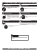
STOW CUTTER 1 CE SAW — RULES FOR SAFE OPERATION Saw Transportation Safety Machine Operation And Safety Decals ■ DO NOT use the handle bars and/or front pointer as lifting points. The CUTTER 1 CE saw is equipped with a number of operation and safety decals. (Figure 1) Should any of these decals become unreadable, replacements can be obtained from your dealer. ■ ALWAYS use ramps capable of supporting the weight of the saw and the operator to load and unload the saw.
STOW CUTTER 1 CE SAW — SPECIFICATIONS (SAW) G C B A F E Side View D Front View Figure 2. CUTTER 1 CE Dimensions Table 1. Cutter 1 CE (CD6CE13H18) Specifications REFERENCE LETTER A B C D E F G DESCRIPTION Width Rear Wheel Base Front Wheel Base Handle Bar Width Maximum Spindle RPM Arbor Size Maximum Cutting Depth Sound Pressure at Operator's Position Vibration * DIMENSION (cm) 37.0 In. (94 cm) 32.0 In. (80 cm) 54.5 In. (138 cm) 21.5 In. (55 cm) 17.0 In. (40 cm) 10.0 In. (25.4 cm) 21.5 In.
STOW CUTTER 1 CE SAW — SPECIFICATIONS (ENGINE) Table 2. Specifications (Engine) Model HONDA GX390K1QWT2/GX390U1QWT2 Type Air-cooled 4 stroke, Single Cylinder, OHV, Gasoline Engine Bore X Stroke 3.5 in. X 2.5 in. (88 mm x 64 mm) Displacement 23.7 cu-in. (389 cc) Max Output Engine Fuel Tank Capacity Fuel Lube Oil Capacity 12.9 bhp (9.6kW, 13PS) @ 3600 R.P.M. Approx. 1.72 U.S. Gallons (6.5 Liters) Unleaded Automobile Gasoline 86 Octane or higher 1.16 US qt (1.
STOW CUTTER 1 CE SAW — GENERAL INFORMATION Intended Use Power Plants Operate the CUTTER 1 CE Saw, tools and components in accordance with the manufacturer's instructions. Use of any other tools for stated operation is considered contrary to designated use. The risk of such use lies entirely with the user. The manufacturer cannot be held liable for damages as a result of misuse. The CUTTER 1 CE saw is classified in the industry as a "low" powered saw.
STOW CUTTER 1 CE SAW — CONTROLS & COMPONENTS CONTROLS & COMPONENTS 10. Belt Tension Adjuster – Adjusts belt tension. Figures 3 shows the location of the basic controls or components for the CUTTER 1 CE. Listed below is a brief explanation of each control or component. 11. Front Pointer – Front pointer wheel assists in straight tracking. 1. 12. Front Pointer Arm – Stows up for storage and pivots down for use.
STOW CUTTER 1 CE SAW — BASIC ENGINE BASIC ENGINE Figure 4. Engine Controls and Components Initial Servicing 6. The engine (Figure 4) must be checked for proper lubrication and filled with fuel prior to operation. Refer to the manufacturer's engine manual for instructions & details of operation and servicing. Choke Lever – Used in the starting of a cold engine, or in cold weather conditions. The choke enriches the fuel mixture. 7.
STOW CUTTER 1 CE SAW — PREPARATION/PRE-INSPECTION PREPARATION / PRE-INSPECTION 1. Read and fully understand this manual, the safety intructions in particular, and the engine manufacturer's manual supplied with the saw. NOTE Reference manufacturer engine manual for specific servicing instructions. UPPER LIMIT 2. Select the correct blade for each application. Refer to the Blades and Blade Placement sections on pages 19 through 21 for further information. 3. Check blade for wear or damage.
STOW CUTTER 1 CE SAW — PREPARATION/PRE-INSPECTION Guards And Covers WARNING NEVER operate the saw without blade guards and covers in place. DO NOT operate with the front of the blade guard raised. The blade exposure cannot exceed 180 degrees during operation. Adhere to the safety guidelines or other applicable local regulations. V-belt Alignment and Tensioning This saw is equipped with premium V-belts that have been aligned and tensioned by factory personnel.
STOW CUTTER 1 CE SAW— BLADES SPECIFIC TOOLS TO BE USED 1. Drive Pin Hole – A commonly located hole on the diamond blade core that prevents operational blade slippage between the inner & outer blade flanges (collars). Inspect the diameter of the hole to ensure there is no distortion, and that a snug fit develops between the hole and drive pin. 2. Stress Relief Holes (Gullets) – Check the steel core for cracks that may have propagated from the slots and/or gullets.
STOW CUTTER 1 CE SAW— BLADE PLACEMENT Table 4. MATERIAL LISTING AND BLADE SELECTION Material Blade Cured Concrete Cured Concrete Blade Green Concrete Green Concrete Blade Asphalt Asphalt Blade Asphalt over Concrete Asphalt/Concrete Blade Block, Brick, Masonry, Refractories Masonry Blade Tile, Ceramic, Stone Tile Blade BLADE PLACEMENT Refer to Figure 11. Diamond Blades Selecting the diamond blade TYPE and GRADE defines how the blade will perform both in cutting speed and blade life.
STOW CUTTER 1 CE SAW— BLADE PLACEMENT 6. Inner Flange (Collar) - This flange is fixed upon the spindle. The inside surface of the flange must be free of debris and permit a tight closure on the surface of the blade. Blade Removal and Replacement 1. Set the ENGINE ON/OFF switches to the "OFF" position to prevent accidental starting. 2. Place the saw on a stable level working surface. 3. Ensure the blade is raised and the raise/lower crank is locked into position.
STOW CUTTER 1 CE SAW— RAISE/LOWER AND DEPTH STOP Raise/Lower and Depth Stop Setting the Depth Stop The saw is equipped with a Raise/Lower and Depth Stop Assembly that is supported by the following components. (Figure 13) 1. Lift the Adjusting Hand Crank to unlock (disengage) the Depth Stop. 1. Adjusting Hand Crank Assembly 2. Rotate the crank to raise or lower the blade to the desired depth. 3. Lower the crank into one of the lock position holes (Item 6). 2. Raise/Lower Acme Screw 3. Jack Arm 4.
STOW CUTTER 1 CE SAW — INITIAL START-UP INITIAL START-UP CAUTION NEVER place hands or feet inside the belt guard or blade guard while the engine is running. ALWAYS shut the engine down before performing any kind of maintenance service on the saw CAUTION DO NOT attempt to operate the saw until this manual has been read and thoroughly understood. Engine operating steps may vary. See included engine manufacturer's operating manual. 1.
STOW CUTTER 1 CE SAW — INITIAL START-UP Figure 18. Engine Stop Switch (Handlebar) The CLOSED position of the choke lever enriches the fuel mixture for starting a COLD engine. The OPEN position provides the correct fuel mixture for normal operation after starting, and for restarting a warm engine. NOTE Figure 20. Throttle Lever 7. Grasp the starter grip (Figure 21) and slowly pull it out. The resistance becomes the hardest at the compression point. Pull the starter grip briskly and smoothly for starting.
STOW CUTTER 1 CE SAW — OPERATION The Engine Stop Switch located on the handlebar (Figure 18) serves both as an Emergency Engine Shut-Off and as the primary ON/OFF switch. This allows the operator to shutdown the saw safely away from moving parts. OPERATION WARNING NOTE ALWAYS cut with the saw at FULL THROTTLE. Attempting to cut with the saw at less than full throttle could cause the blade to bind or stop abruptly in the slab resulting in serious injury to the operator or others in the area.
STOW CUTTER 1 CE SAW — OPERATION Restarting After Intervention If cutting is interrupted where the engine stops or is turned off while the blade is still in the cut: c. Lift the guard up and back until the retaining spring acts to hold the guard in the “up” posiiton. d. Return to the operator postion between the handles. a. Turn Engine Off switches to "OFF" e. Restart the blade rotation. b. Raise the blade out of the cut f.
STOW CUTTER 1 CE SAW — MAINTENANCE MAINTENANCE CAUTION See the engine manual supplied with your machine for appropriate engine maintenance schedule and troubleshooting guide for problems. General maintenance practices are crucial to the performance and longevity of your saw.
STOW CUTTER 1 CE SAW — MAINTENANCE Engine oil change: Change engine oil the first month or 20 hours of operation. Then every 3 months/or 50 HOURS of operation. See Engine Owner’s Manual for detailed information. Drain the used oil while the engine is warm by the following method: Refer to Figure 23. 1. Place an oil pan or suitable container below the engine drain plug to catch the used oil. 2. Remove the filler cap/dipstick and the drain plug. 3. Drain the oil completely and reinstall the drain plug.
STOW CUTTER 1 CE SAW — OPTIONAL WATER TANK WATER TANK KIT (OPTION) An optional water tank kit is available for use with the CUTTER 1 CE Saw. The following steps are instructions for the assembly of the kit onto your CUTTER 1 CE Saw. 5. After determining the correct spacer length, place the spacers (item 12, Figure 24) between the engine block and the tank shelf bracket and secure the assembly with the 3/8" hardware (items 6, 8, and 10). Use the appropriate length bolt (item 6) for your application.
STOW CUTTER 1 CE SAW — OPTIONAL WATER TANK 9 Place the Water Tank (with the hose assembled), onto the Tank Shelf so the valve and hose are resting in the notch of the top of the Tank Shelf. (Figure 26) 10. Place the Bungee Cord (item 4) over the Water Tank (item 14) so it securely holds the tank onto the Shelf. 11. Disconnect the existing water hose from the saw blade guard and connect instead, the new hose using the Swivel Connector.
STOW CUTTER 1 CE SAW — TROUBLESHOOTING (SAW) TABLE 5. BLADE TROUBLESHOOTING SYMPTOM POSSIBLE PROBLEM Blade slows or stops cutting. Blade does not cut straight and/or true. Blade discoloring, crackling and/or wearing excessively. NOTE SOLUTION Blade too hard for the material being cut? Consult Dealer or Multiquip for correct blade. Try cutting very soft material (sandstone, silica brick, cinder block) to "Redress" the blade.
STOW CUTTER 1 CE SAW — TROUBLESHOOTING (ENGINE) TABLE 6. TROUBLESHOOTING (ENGINE) SYMPTOM Difficult to star t, "fuel is available, but no SPARK at spark plug". Difficult to star t, "fuel is available, and SPARK is present at the spark plug". Difficult to star t, "fuel is available, spark is present and compression is normal". Difficult to star t, "fuel is available, spark is present and compression is low". POSSIBLE CAUSE SOLUTION Spark plug bridging? Check gap, insulation or replace spark plug.
STOW CUTTER 1 CE SAW — TROUBLESHOOTING (ENGINE) TABLE 6. TROUBLESHOOTING (ENGINE, CONTINUED) SYMPTOM POSSIBLE CAUSE Air cleaner not clean? SOLUTION Replace air cleaner. Check float adjustment. "Weak in power" compression is proper and does not misfire. Improper fuel level in carburetor? Rebuild carburetor. Defective spark plug? Clean or replace spark plug. Improper spark plug gap? Set to proper gap. Water in fuel system? Flush fuel system and replace with correct type fuel.
TERMS AND CONDITIONS OF SALE — PARTS Terms and Conditions of Sale STOW Construction Equipment PAYMENT TERMS Terms of payment for unit sales are 2% 15 days net 30 days from date of invoice unless otherwise specifically stated on our invoice. Parts invoices have terms of net 10 days. Minimum parts billing is $15.00 net. Applicable discounts will be computed on merchandise value only. Late charges will be assessed at prevailing rates.
NOTE PAGE STOW CUTTER 1 CE — OPERATION MANUAL — REV.
OPERATION MANUAL HERE’S HOW TO GET HELP PLEASE HAVE THE MODEL AND SERIAL NUMBER ON-HAND WHEN CALLING PARTS DEPARTMENT 800-427-1244 FAX: 800-672-7877 310-537-3700 FAX: 310-637-3284 SERVICE DEPARTMENT 800-478-1244 FAX: 310-537-4259 310-537-3700 TECHNICAL ASSISTANCE 800-478-1244 FAX: 310-631-5032 WARRANTY DEPARTMENT 800-421-1244, EXT. 279 FAX: 310-537-1173 310-537-3700, EXT. 279 SALES DEPARTMENT 310-661-4242 FAX: 310-604-9237 877-289-7869 (877-BUY-STOW) © COPYRIGHT 2007, MULTIQUIP INC.